Mitutoyo Corporation 20-1, Sakado 1-Chome, Takatsu-ku, Kawasaki-shi, Kanagawa 213-8533, Japan
Date of publication: December 1, 2021
Printed in Japan
4
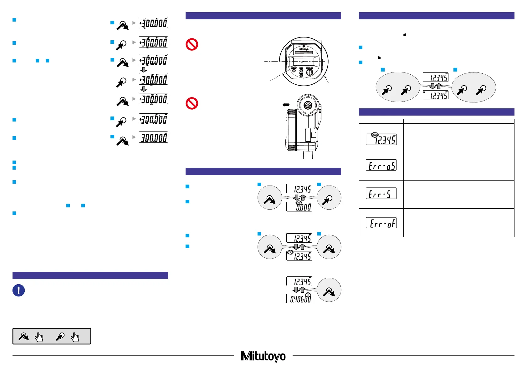
Briey press the [PRESET] key until [3] is displayed.
5
Press and hold the [PRESET] key.
》 The number in the next digit blinks.
6
Repeat steps
4
and
5
, so that [3], [0], [0], [0], [0], and [0] are
displayed for the digits.
7
Press and hold the [PRESET] key until [P1] blinks.
8
Briey press the [PRESET] key.
》 [P1] is cleared and registration is complete.
2) Reference point setting
1
Remove any dirt or dust from both the anvil and spindle measurement surfaces and the gage.
2
Bring the measurement surfaces into light contact with each other (or pinch the gage and bring the spindle into light
contact with the gage), stop momentarily, and then apply the appropriate measuring force (see "3. Precautions for
Use
■
Measuring Force").
3
Press the [PRESET] key.
》 [P1] or [P2] blinks, and the registered preset value (zero if not registered) is displayed.
Tips
• Press and hold the [HOLD] key to switch between P1 and P2.
• To change the preset value, see steps
2
through
7
in "1) Reference point registration".
4
Briey press the [PRESET] key.
》 [P1] or [P2] is cleared.
Tips
• The display of this product automatically turns off if not used for 20 minutes or more. To display again, either rotate
the thimble or press the [ZERO/ABS] key.
• If the [PRESET] key is accidentally pressed during measurement, press the [ZERO/ABS] key to return to the former
state. If this does not enable the product to recover, perform "5. PRESET Value (Reference Point) Setting" once
more.
• Do not handle gages (gauge blocks, setting standards for outside micrometers, etc.) with your bare hands. Use
precision work gloves such as cotton gloves.
6. Measurement Method
• Be sure to perform reference point setting before measurement.
• Bring the measurement surface of the spindle slowly into contact with the workpiece. Moving too quickly
could deform the workpiece and affect measurement results.
Gradually and lightly bring the measurement surfaces into contact with the workpiece in the same orientation and
conditions as for reference point setting, apply the appropriate measuring force, and then read the display value
(see "3. Precautions for Use
■
Measuring Force").
5
4
PRESET
PRESETPRESET
7
8
PRESET
PRESET
6
PRESET
PRESET
Key operation icon
=
> 2 s
=
< 1 s
7. Display Unit Angle Adjustment
Turn the bezel to rotate the display unit. After mounting the product, adjust it to an angle which is easy to read.
The display unit can be rotated up to 240° to the right (clockwise) and 90° to the left.
The specication of the display unit does
not allow rotations in excess of the above
angles for the stopper. Exercise caution and
do not rotate beyond the specied range.
This may cause damage.
Do not pull the display unit out or press it in
forcefully. This may cause damage.
8. Key Functions
■ [ZERO/ABS] Key
1
Briey press the [ZERO/ABS] key.
》 [INC] is displayed, and the display is set
to zero.
2
Press and hold the [ZERO/ABS] key (for at
least 2 seconds).
》 [INC] is cleared, and the length from the
reference point (anvil measurement surface)
is displayed.
■ [HOLD] Key
1
Press the [HOLD] key.
》 [H] is displayed, and the display value is held.
2
Press the key again to release the value.
■ [in/mm] Key (in/mm Products Only)
• Press the [in/mm] key.
》 [in] and [mm] switch back and forth each time the key is
pressed.
330°
ZERO/ABSZERO/ABS
HOLD
HOLD
in / mm
3
9. Function Lock Function (Preventing Accidental Operation)
This product has the Function Lock function, which disables the PRESET function and ZERO/ABS function in order to
avoid accidental changes to the reference point position.
Setting the Function Lock causes [
] on the display unit to light up and disables the [PRESET] key, [ZERO/ABS] key,
and [in/mm] key (in/mm product only), with only the Hold operation function enabled.
1
First press and hold the [HOLD] key, and then additionally press and hold the [ZERO/ABS] key (for at least 2
seconds).
》 [H] and [
] light up in sequence ([H] turns off rst).
2
Perform the same operation to release the Function Lock.
HOLD
+
ZERO/ABSHOLD
+
ZERO/ABS
21
10. Errors and Troubleshooting
Error display Causes and countermeasures
Power Voltage Drop
The battery voltage is low. Replace the batteries promptly.
Counting Error
A counting error has occurred due to excessive speed or noise. Try removing
the batteries and reinstalling.
If it does not recover after being reset, repair is required: please contact the
agent where you purchased the product or a Mitutoyo sales representative.
Counting Error
Initial setting of the control unit failed, or a counting error has occurred due to a
sensor signal error. Try removing the batteries and reinstalling.
If it does not recover after being reset, repair is required: please contact the
agent where you purchased the product or a Mitutoyo sales representative.
Display Overow
The display value exceeds ±999.999. Rotate the thimble in the opposite
direction so that it starts counting again correctly.
 Loading...