Do you have a question about the Mitutoyo ID-C Series and is the answer not in the manual?
Explains document structure, conventions, and key notations for user understanding.
Defines the meaning of brackets, quotation marks, and numbers used in the manual.
Explains how keys and operations are represented in the manual.
Details hazard symbols (DANGER, WARNING, CAUTION, NOTICE) and their meanings.
Explains symbols for prohibited and mandatory actions.
Explains symbols for tips and reference locations.
Provides precautions for handling lithium metal batteries (CR2032).
Guidelines for proper product handling and application to prevent damage.
Recommendations for suitable environments to avoid product malfunction or failure.
Instructions for cleaning and maintaining the product.
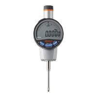
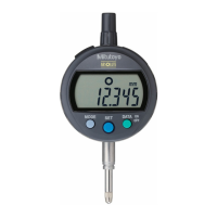
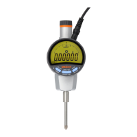
Introduces the Digimatic indicator, its types, and key features.
Details the names and dimensions of the main unit components for ISO/JIS and ASME models.
Explains the various elements and indicators displayed on the product's LCD screen.
Lists the items included as standard accessories with the product.
Instructions for securely mounting the product to a stand or jig for measurement.
Describes how to mount optional accessories like lifting levers or knobs.
Details the procedure for replacing the contact point on the product.
Provides instructions on how to adjust the display angle for optimal readability.
General precautions to be observed before operating the product.
Step-by-step guide for installing and replacing the product's battery.
Instructions on how to turn the product's power ON and OFF.
Explains the two main operating modes: measurement and parameter setting.
Details how to switch between Absolute (ABS) and Incremental (INC) measurement systems.
Explains how to change the unit system between millimeters (mm) and inches (in).
Describes the process of absolute measurement, including setting origin and preset values.
Explains incremental measurement, zeroing the display, and measuring differences.
Details the peak detection function, including runout, max, and min value displays.
Covers setting allowable values for GO/NG judgments and displaying results.
Explains how to fix (hold) the displayed value on the screen.
Describes how to assign different functions to the product's keys.
Instructions on connecting to external devices for data output.
Lists the available parameter items that can be configured on the product.
Guide on selecting between Standard 1, Standard 2, and Peak Detection measurement modes.
Explains how to select the unit system (mm or in) for the display.
Details how to set the counting direction for plunger movement.
Instructions on selecting the minimum display amount (resolution) for the product.
Covers setting the display method and allowable values for tolerance judgment.
Step-by-step guide for setting the upper and lower allowable limits for measurements.
Explains how to use calculation functions and set the calculation coefficient.
Details how to turn the analog bar display ON/OFF and adjust its scale.
Describes how to assign functions to the product's keys via short presses.
Explains how to enable or disable the function lock to prevent unintended operations.
Accessing and configuring other miscellaneous functions like calibration warnings and auto-off.
Details how to adjust the measuring force by adding/removing coil springs or weights.
Procedure for adding or removing the internal coil spring of the product.
Steps for attaching or detaching the weight to adjust measuring force.
Instructions for replacing the contact point on low measuring force models.
Describes the pin assignments and signal definitions for the product's I/O connector.
Explains the data format for DIGIMATIC output and provides timing charts.
Lists detailed technical specifications for standard ABSOLUTE Digimatic Indicator models.
Details the technical specifications for the low measuring force type models.
Outlines general specifications applicable to all models, including power, scale, and functions.
| Model | ID-C Series |
|---|---|
| Display | LCD |
| Resolution | 0.01mm |
| Data Output | Yes |
| Power Supply | SR44 battery (1 pc.) |
| Functions | Zero setting |
| Main Material | Steel |