Do you have a question about the Mitutoyo ID-F125 and is the answer not in the manual?
Explains general warnings and safety alert symbols.
Details different types of notes (IMPORTANT, NOTE, TIP) for user guidance.
Precautions for connecting and using the AC adapter and power supply.
General precautions to avoid instrument failure or malfunction.
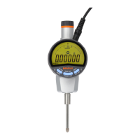
Identifies and labels the main components of the instrument.
Explains the various elements displayed on the instrument's LCD screen.
Instructions for mounting the instrument onto a stand or fixture.
Steps for attaching the lifting lever to the instrument.
Procedure for installing the release mechanism.
Steps for connecting the instrument to a power source.
How to turn the instrument on and off.
Procedures for initial setup and configuration of the instrument.
Instructions on setting the absolute origin or preset value for measurements.
Overview of the different measurement modes available on the instrument.
Describes the standard mode for general measurements.
Details the mode for setting and checking upper/lower tolerance limits.
How to use the mode to hold the maximum measured value.
How to use the mode to hold the minimum measured value.
Operation for measuring run-out or total indicator runout.
Explains the analog scale and pointer on the LCD.
Explains how to switch the analog display range.
How to center the analog display pointer.
How to reverse the spindle's counting direction.
How to lock and unlock the instrument's keys.
Details the pin assignment of the data output connector.
Explains the format of the data transmitted from the instrument.
Illustrates the timing relationships for data output signals.
Guide to using the optional Digimatic Presetter for setup.
Provides detailed technical specifications for the instrument.
Lists the items included as standard accessories with the instrument.
Lists available optional accessories for the instrument.
| Brand | Mitutoyo |
|---|---|
| Model | ID-F125 |
| Category | Measuring Instruments |
| Language | English |