EasyManua.ls Logo

Mitutoyo ID-C1012MNXB User Manual

Mitutoyo ID-C1012MNXB
120 pages
To Next Page IconTo Next Page
Page #1 background imageLoading...
Page #1 background image
No. 99MAH056A1
Date of publication: April 27, 2022
User's Manual
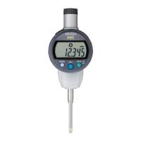
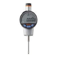
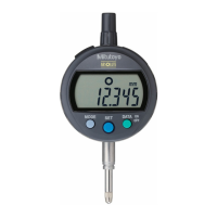
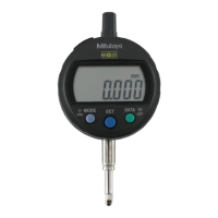
ABSOLUTE Digimatic Indicator
ID-C
ID-C0512NX ID-C0512NXB
ID-C0512MNX ID-C0512MNXB
ID-C0512ENX ID-C0512ENXB
ID-C0512CNX ID-C0512CNXB
ID-C0512CMNX ID-C0512CMNXB
ID-C0512CENX ID-C0512CENXB
ID-C1012NX ID-C1012NXB
ID-C1012MNX ID-C1012MNXB
ID-C1012ENX ID-C1012ENXB
ID-C1012CNX ID-C1012CNXB
ID-C1012CMNX ID-C1012CMNXB
ID-C1012CENX ID-C1012CENXB

Table of Contents

Question and Answer IconNeed help?

Do you have a question about the Mitutoyo ID-C1012MNXB and is the answer not in the manual?

Mitutoyo ID-C1012MNXB Specifications

General IconGeneral
ModelID-C1012MNXB
CategoryMeasuring Instruments
Resolution0.01 mm
Accuracy±0.02 mm
DisplayLCD
BatterySR44
Protection RatingIP67
MaterialStainless Steel
WeightApprox. 200 g
Data OutputYes

Summary

3 Basic Usage

3.2 Installing and Replacing the Battery

Detailed procedure for installing and replacing the CR2032 lithium metal battery.

3.3 Power ON/OFF

Instructions on how to turn the indicator's power on and off.

3.4 Measurement Mode and Parameter Setting Mode

Explanation of the two primary operating modes: measurement and parameter setting.

3.5 Switching Measurement Systems

How to switch between Absolute (ABS) and Incremental (INC) measurement modes.

4 Measurement Method

4.1 Absolute Measurement (ABS)

Sets measurement origin and measures workpiece dimensions using the ABS system.

4.2 Incremental Measurement (INC)

Sets a reference point and measures dimensional differences using the INC system.

4.3 Peak Detection

Measures and displays peak values (runout, max, min) during workpiece movement.

4.4 Tolerance Judgment

Configures GO/NG judgment by setting upper and lower allowable values.

4.7 Externally Outputting the Displayed Value

Connects to external devices for data output via a connection cable.

5 Setting Parameters

5.6 Selecting the Tolerance Judgment Result Display Method and Setting Allowable Values

Configures tolerance judgment display and sets upper/lower limit values.

5.7 Setting Calculation Function Selection and Calculation Coefficient

Enables calculation measurement and setting of the calculation coefficient.

7 Low Measuring Force Types

8 Error Displays and Countermeasures

9 Input/Output Functions

10 Specifications

12 Off-Site Repairs (Subject to Charge)

Related product manuals