Do you have a question about the Mitutoyo ID-C112GXB and is the answer not in the manual?
Explains safety symbols (Signal Words and Safety Alert Symbols) used in the manual.
Describes different types of notes (IMPORTANT, NOTE, TIP) used for operator guidance.
Provides warnings and precautions regarding battery handling and safety.
Provides warnings and precautions for the disposal of the instrument and its components.
Details the terms and conditions of the product warranty.
Explains compliance with export trade control regulations.
Introduces the instrument, its purpose, and basic operational modes.
Lists the capabilities and functions of the instrument.
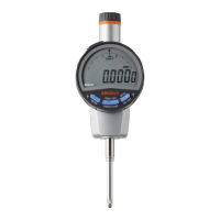
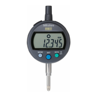
Identifies and illustrates the different parts of the instrument and provides dimensions.
Explains the components and layout of the instrument's display unit.
Lists the technical specifications of the instrument.
Lists the items included as standard accessories with the instrument.
Lists optional accessories available for the instrument.
Guides the user through battery installation and initial setup procedures.
Explains how to adjust the angle of the display unit for better visibility.
Provides instructions on how to mount the instrument on a bore gage.
Describes how to turn the instrument on and off.
Explains the different settings and operations within the measurement mode.
Details how to set preset values for measurement.
Explains how to edit numerical values for preset and tolerance settings.
Describes how to switch to and use the minimum value detection mode.
Explains how to hold the displayed measurement value when not connected to a data processor.
Details how to output the display value to a data processor.
Explains how to save and load measurement data in the instrument's memory.
Describes how to switch between inch and metric display units.
Explains how to enter and navigate the setup mode for various parameters.
Details how to enable/disable and set tolerance judgment values.
Explains how to change the display resolution of the instrument.
Describes how to adjust the analog bar graduation settings.
Explains how to enable or disable the key-lock function to prevent accidental operations.
Introduces other functions like PC communication and unit display settings.
Guides on enabling PC communication with the instrument using a setup kit.
Explains how to hide or display the analog bar on the instrument screen.
Describes how to enable or disable the FAST mode for improved minimum value detection.
Guides on performing a factory reset of the instrument's settings.
Details how to connect the instrument to a data processor using a cable.
Describes the pin assignments and configuration of the output connector.
Explains the format of the data outputted by the instrument.
Illustrates the timing sequence for data output signals.
| Model | ID-C112GXB |
|---|---|
| Display Type | LCD |
| Data Output | Yes |
| Material | Stainless Steel |
| Measuring Range | 0-12.7 mm |
| Resolution | 0.001 mm |
| Power Supply | SR44 battery (1 pc.) |
| Functions | Absolute/Incremental measurement, Data hold, Zero setting |