EasyManua.ls Logo

Mitutoyo ID-C0512ENXB User Manual

Mitutoyo ID-C0512ENXB
120 pages
To Next Page IconTo Next Page
Page #1 background imageLoading...
Page #1 background image
No. 99MAH056A1
Date of publication: April 27, 2022
User's Manual
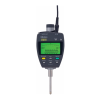
ABSOLUTE Digimatic Indicator
ID-C
ID-C0512NX ID-C0512NXB
ID-C0512MNX ID-C0512MNXB
ID-C0512ENX ID-C0512ENXB
ID-C0512CNX ID-C0512CNXB
ID-C0512CMNX ID-C0512CMNXB
ID-C0512CENX ID-C0512CENXB
ID-C1012NX ID-C1012NXB
ID-C1012MNX ID-C1012MNXB
ID-C1012ENX ID-C1012ENXB
ID-C1012CNX ID-C1012CNXB
ID-C1012CMNX ID-C1012CMNXB
ID-C1012CENX ID-C1012CENXB

Table of Contents

Question and Answer IconNeed help?

Do you have a question about the Mitutoyo ID-C0512ENXB and is the answer not in the manual?

Mitutoyo ID-C0512ENXB Specifications

General IconGeneral
ModelID-C0512ENXB
CategoryMeasuring Instruments
TypeDigital Indicator
Accuracy±0.003 mm
DisplayLCD
Measuring Range0 to 12.7 mm
Resolution0.001 mm
Power SupplySR44 battery
Data OutputYes
FunctionsZero-setting

Summary

Safety Precautions

Precautions for Use

Electromagnetic Compatibility (EMC)

1 Overview

2 Preparations before Use

3 Basic Usage

3.2 Installing and Replacing the Battery

Step-by-step guide for battery installation and replacement.

3.4 Measurement Mode and Parameter Setting Mode

Overview of the two main operating modes of the indicator.

4 Measurement Method

4.1 Absolute Measurement (ABS)

Explains how to set the measurement origin and measure dimensions.

4.2 Incremental Measurement (INC)

Details how to set a reference point and measure dimensional differences.

4.3 Peak Detection

Describes how to detect and display peak values during measurement.

4.4 Tolerance Judgment

Covers setting upper/lower limits for pass/fail (GO/NG) judgments.

5 Setting Parameters

5.1 Selecting Parameter Items

Lists the available parameter items that can be configured.

5.2 Selecting Measurement Mode

Guide to selecting between Standard 1, Standard 2, and Peak Detection modes.

5.5 Selecting Resolution

How to select the minimum display amount (resolution) for measurements.

5.6 Selecting the Tolerance Judgment Result Display Method and Setting Allowable Values

Configures how tolerance judgment results are displayed and sets allowable values.

5.7 Setting Calculation Function Selection and Calculation Coefficient

Enables calculation measurement by multiplying movement by a coefficient.

7 Low Measuring Force Types

8 Error Displays and Countermeasures

9 Input/Output Functions

10 Specifications

11 Accessories (Optional)

12 Off-Site Repairs (Subject to Charge)

Related product manuals