Do you have a question about the Mitutoyo ID-C and is the answer not in the manual?
Explains hazard warning symbols and their meanings.
Details symbols for prohibited and mandatory actions.
Explains symbols for tips and reference locations.
Provides critical safety guidelines for handling lithium metal batteries.
Guidelines on proper application and handling to prevent damage.
Recommendations for suitable environments to ensure product performance.
Explains document structure, symbols, and reading conventions for clarity.
Explains the meaning of brackets, quotation marks, and numbers used.
Defines the symbols and conventions used to indicate key presses and operations.
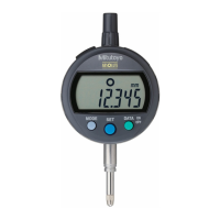
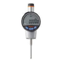
Provides a general description of the ABSOLUTE Digimatic Indicator ID-C.
Details the physical parts and their dimensions with diagrams.
Explains the various icons and information shown on the LCD display.
Lists the items included in the product package.
Instructions for orienting the product for use.
Procedures for securely attaching the indicator to stands or jigs.
Describes how to attach optional backs for mounting.
Guides on installing the lifting lever and optional lifting knob.
Step-by-step instructions for replacing the contact point.
How to adjust the display's viewing angle for better readability.
Warnings and advice to prevent malfunction or damage before initial operation.
Detailed steps for battery installation and replacement.
Instructions on how to turn the device's power on and off.
Explains the two primary operating modes of the indicator.
How to switch between Absolute (ABS) and Incremental (INC) measurement modes.
Guides on changing the unit display between millimeters and inches.
How to set the origin and measure workpiece dimensions using ABS mode.
How to set a reference point and measure dimensional differences using INC mode.
Procedures for detecting and displaying peak values like runout, max, and min.
How to set allowable values for pass/fail (GO/NG) judgments.
Instructions on how to freeze the displayed measurement value.
How to assign different functions to the product's keys.
Steps for connecting to external devices to output measurement data.
Lists and describes the available parameter settings for the indicator.
How to choose between Standard 1, Standard 2, and Peak Detection modes.
Guide to setting the unit system to mm or inches.
How to set the direction of counting for plunger movement.
How to choose the minimum display amount (resolution) for measurements.
How to configure tolerance judgment display and set upper/lower limits.
How to enable calculation functions and set coefficients.
How to turn the analog bar display on/off and set its scale.
How to customize the functions assigned to key presses.
How to enable or disable function lock to prevent unintended changes.
Accessing settings for calibration warning, Digimatic output, and auto-off.
Details the pin assignments and electrical specifications of the I/O connector.
Explains the data format for DIGIMATIC output and the timing chart.
| Model | ID-C |
|---|---|
| Category | Measuring Instruments |
| Display | LCD |
| Measuring Force | 1.5 N or less |
| Resolution | 0.01mm |
| Battery | SR44 |
| Functions | Data output |