Printed in Japan
Mitutoyo Corporation 1-20-1 Sakado, Takatsu-ku, Kawasaki City, Kanagawa 213-8533
1. Names and Dimensions of Components
■ 25.4 mm stroke model
ID-C125XB, ID-C125MXB, ID-C125EXB, ID-C1025XB, ID-C1025MXB, ID-C1025EXB
Unit: mm
11 (0.43 in)
ø59 (2.32 in)
1.02 in 3.30 in
2.67 in
1.66 in
0.68 in
57.7 (2.27 in)
1/4 in
84.8
70
40.8
26
7.3
19.5
ø9.52
3/8 in
-0.03
0
ø8
-0.009
0
ø19.2 (0.76 in)
M2.5X0.45
No.4-48UNF
31.5 (1.24 in)
ISO/JIS
type
AGD
type
12
11
10
9
3
7
2
8
1
4
5
6
■ 50.8 mm stroke model
ID-C150XB, ID-C150MXB, ID-C150EXB, ID-C1050XB, ID-C1050MXB, ID-C1050EXB
ø59 (2.32 in)
ø8
-0.009
0
M2.5X0.45
11 (0.43 in)
2.05 in 4.32 in
3.74 in
2.62 in
0.68 in
85.2 (3.35 in)
1/4 in
110.6
97.3
65.3
52
7.3
19.5
ø19.2 (0.76 in) 31.5 (1.24 in)
ISO/JIS
type
AGD
type
No.4-48UNF
ø9.52
3/8 in
-0.03
0
7
12
11
10
9
8
1
2
3
4
5
6
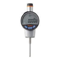
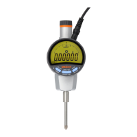
① Cap
② Output connector (with cap)
③ Display (LCD)
④[MODE] key/[MODE in/mm] key*
*
Except ID-C125XB, ID-C1025XB, ID-C150XB, and ID-C1050XB
⑤[DATA ON/OFF] key
⑥[SET] key
⑦ Battery holder
⑧ Release mounting hole (with rubber cap)
⑨ Flat back
⑩ Stem
⑪ Spindle
⑫ Contact point
Unit: mm
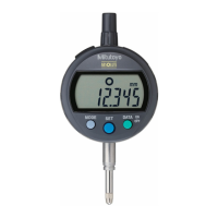
■ Display (LCD)
① Reverse count display
② Function lock display
③ Low battery voltage display
④ INC display
⑤ Calculation function display
⑥ Tolerance judgment result display (-NG)
⑦ Tolerance judgment result display (OK)
⑧ Tolerance judgment result display (+NG)
⑨ Preset display
⑩ Unit display
⑪ Measured value display
(tolerance judgment enlarged display)
⑫ Hold display
⑬ Sign display
2. Installing (Replacing) the Battery
• Be sure to use SR44 (silver oxide button battery, part No. 938882) for the battery.
• The product may display an error or malfunction if the battery holder is not mounted correctly.
• If the product will be out of use for 3 months or more, remove the battery and store it
separately, to prevent damage to the product due to battery fluid leakage.
• Do not use a pointed object or excessive force to remove the battery holder. This may damage
the battery holder.
3
1
2
4
SR44
in/mm model
in/mm model
5
1
Use a flathead screwdriver or similar to remove the battery holder.
2
If replacing an existing battery, remove the old battery.
3
Insert a new battery into the battery holder with the "+" symbol facing the display (LCD).
4
Attach the battery holder.
⇨ [------] display lights up.
5
Press the [SET] key twice.
⇨ Measurement mode (absolute measurement) starts.
Tips
• If absolute measurement does not begin even after pressing the [SET] key twice, reinstall the
battery.
• All settings are cleared when the battery is removed. All settings must be reconfigured.
Safety Precautions
To ensure operator safety, use this product in conformance with the directions, functions
and specifications given in this User's Manual.
Use under other conditions may compromise safety.
•
Always keep batteries out of reach of children. If swallowed, consult a physician immediately.
• Batteries should never be short-circuited, disassembled, deformed or come in contact with
extreme heat or flames.
• If battery alkaline liquid comes in contact with the eyes, flush eyes immediately with clean
water and consult a physician. If battery alkaline liquid comes in contact with the skin,
flush the exposed area thoroughly with clean water.
Never attempt to charge the primary battery. Never reverse the positive-negative terminals
when mounting. Improper battery handling or mounting may cause the battery to explode,
cause battery leakage and/ or serious bodily injury or malfunctioning.
• Do not disassemble or modify. This may cause damage.
• Do not use or store the product in a place with sudden temperature changes. Adapt the
product to ambient temperature before use.
• Do not store the product in a place with high humidity or a lot of dust. Also, avoid usage in
places exposed to splashes of water or coolant.
• Do not apply excessive force or subject to sudden impacts such as dropping.
• Be sure to perform reference point setting before measurement.
• Remove dust, cutting chips, etc. before and after use.
• Do not write numbers, etc. with an electric pen. This may cause damage.
• Do not operate the keys with a pointed object (such as a screwdriver or ballpoint pen).
•
Avoid loads in the vertical direction relative to the spindle or usage involving torsion to the spindle.
• This product is shipped without installing a battery. Install a battery before use.
• The battery supplied is for confirming the functions and performance of the product. Note
that this battery may not fulfill the expected life.
• When disposing of batteries, follow local laws, regulations, etc.
• Malfunction or damage due to depleted batteries, etc. is not covered by the warranty.
ABS Digimatic Indicator ID-CX
User's Manual
No. 99MAH050A2
Date of publication: November 1, 2020
Key icon operation
=
> 2 s
=
< 1 s
Contents
1. Names and Dimensions of Components ................................................................Page 1
2. Installing (Replacing) the Battery ............................................................................Page 1
3. Setup.......................................................................................................................Page 2
4. Display Angle Adjustment .......................................................................................Page 2
5. Power ON/OFF .......................................................................................................Page 3
6. Operation Modes ....................................................................................................Page 3
7. Switching Measurement System.............................................................................Page 3
8. Switching Unit System ............................................................................................Page 3
9. Measurement Method .............................................................................................Page 3
10. Setting Parameters .................................................................................................Page 4
11. Precautions After Use .............................................................................................Page 6
12. Error Displays and Countermeasures .....................................................................Page 6
13. Output Function ......................................................................................................Page 6
14. Specifications ..........................................................................................................Page 7
15. Accessories (Optional) ............................................................................................Page 7
16. Off-Site Repairs (Subject to Charge) ......................................................................Page 7