Do you have a question about the Mitutoyo ID-U and is the answer not in the manual?
Essential safety guidelines for handling batteries and product usage to prevent injury.
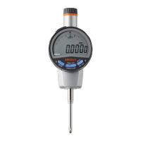
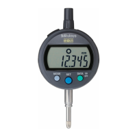
Identification of main components including display, keys, stem, and contact point.
Step-by-step guide for installing or replacing the battery correctly.
Instructions for mounting levers, releases, and replacing contact points.
Procedure for turning the device on and off.
Steps to set the reference point (ORIGIN) for accurate measurements.
Guidance on how to perform measurements and switch counting direction.
Instructions for switching between inch (in) and millimeter (mm) units.
Guidelines for cleaning and storing the product after use.
Explanation of error codes and troubleshooting steps for common issues.
How to output displayed values to external devices via connection cable.
Detailed technical specifications including model, range, resolution, and power.
List of optional accessories available for purchase.
Information regarding malfunctions requiring off-site repair services.
The Mitutoyo ABS Digimatic Indicator ID-U is a precision measuring instrument designed for accurate and reliable dimensional measurements. This user manual provides comprehensive instructions for its safe operation, setup, measurement methods, and maintenance.
The ID-U indicator features an ABS (Absolute) measurement system, which means it retains its origin point even after the power is turned off. This eliminates the need for repeated origin setting, enhancing efficiency. The device displays measured values on an LCD screen, with options for both positive and negative counting directions, and can switch between metric (mm) and imperial (inches) units. It also includes an output function, allowing it to connect to external devices for data processing. The indicator is designed for mounting on a stand or jig, using its stem for stable positioning during measurement.
The manual emphasizes several safety precautions. Users are warned to keep batteries out of reach of children and to avoid short-circuiting, disassembling, deforming, or exposing batteries to extreme heat or flames. In case of battery fluid contact with eyes or skin, immediate flushing with clean water and medical consultation are advised. Charging primary batteries, reversing terminals, or applying excessive force to the device should be avoided to prevent damage or injury. The product should not be disassembled or modified, and should be used and stored in stable temperature and humidity conditions, away from water splashes, coolant, or excessive dust. Dropping the device or subjecting it to sudden impacts is also discouraged.
The ID-U uses an SR44 silver oxide button battery (part No. 938882). To install or replace the battery, a coin or similar tool is used to rotate and remove the battery cap. A new battery is inserted with the "+" symbol facing the LCD. After mounting the cap, the [ORIGIN] key must be pressed for at least one second to ensure proper function. If no value is displayed after battery installation, reinstall the battery. Reference point settings are cleared when the battery is removed, so re-setting the origin is necessary after battery replacement. For long-term storage (3 months or more), the battery should be removed to prevent fluid leakage.
The indicator can be mounted to a stand or jig using its stem. The manual recommends using a slotted holder with a specific diameter (ø8 mm for ID-U1025, ID-U1025M, or ø9.52 mm for ID-U1025E) and advises against fixing the stem directly with a set screw if possible, or tightening it with excessive torque (150 cN·m or more) to avoid hindering spindle movement.
For models with a lifting lever, the spindle should be fixed with padded pliers before inserting the lever and adjusting its orientation. If a release (optional, part No. 540774) is used, the rubber cap must be removed, and the release screwed firmly into the mounting hole. The rubber cap should always be mounted if a release is not used. The release allows for spindle movement of about 10 mm.
When replacing the contact point, the user must turn the contact point while fixing the spindle to prevent damage to the product. The manual illustrates using a rag and two pairs of pliers for this task. Changing contact points may affect external dimensions, measuring force, or measurement directions, and can introduce errors in accuracy. Various optional contact points are available.
The device is turned on and off by pressing the [ON/OFF] key. If the device does not power on, the battery may be depleted and should be replaced. The reference point and counting direction settings are retained even after the power is turned off.
To set the origin, the spindle is moved to the desired reference point, and the [ORIGIN] key is pressed for at least one second. The displayed value will then become 0.00. It is recommended to place the contact point on the workpiece several times to ensure a stable measured value. For accurate reference point setting, the spindle should be lifted at least 0.2 mm above the bottom dead center.
Measurements are performed by gradually and lightly placing the contact point on the workpiece in the same orientation and conditions as used for reference point setting, then reading the indicated value. Striking the workpiece hard can cause deformation and affect measurement results.
The counting direction (positive or negative) can be changed by pressing the [+/-] key. If negative counting is selected and the spindle is pushed in, "REV" will appear on the top left of the LCD. The unit can be switched between inches and millimeters by pressing the [in/mm] key.
The ID-U can output measured data to external devices such as Digimatic mini-processors, display units, or PCs. This requires an optional connecting cable. The manual provides instructions for connecting the cable, ensuring the cap is removed and the connector is inserted firmly. Two types of connection cables (parts No. 905338 and 905409) are available.
After use, the product should be cleaned with a soft cloth moistened with diluted neutral detergent. Organic solvents like thinner should not be used, as they can damage the product. If the spindle cannot move smoothly, it should be cleaned with a cloth moistened with alcohol.
The product should not be stored in places with sudden temperature changes, high humidity, or excessive dust. Before long-term storage (3 months or more), the battery should be removed to prevent damage from fluid leakage.
The manual includes a section on errors and troubleshooting.
Repairs are subject to charge and should be handled by the nearest Mitutoyo dealer or sales office. The manual notes that if fundamental structural components need to be replaced, the device will not retain its ABS origin.
| Display | LCD |
|---|---|
| Type | Digital Indicator |
| Operating Temperature | 0 to 40°C |
| Storage Temperature | -10 to 60°C |
| Range | 0 to 12.7 mm (0 to 0.5 in) |
| Resolution | 0.001 mm (0.00005 in) |
| Power Supply | SR44 battery (1 piece), 938882 |
| Functions | Data output |
| Accuracy | ±0.003 mm (±0.00012 in) |