Printed in Japan
Mitutoyo Corporation, 1-20-1 Sakado, Takatsu-ku, Kawasaki City, Kanagawa 213-8533, Japan
2) Mounting the lifting lever
1
Fix the spindle, using pliers padded with a rag, etc., from the opposite side so that it does not turn.
2
Insert the lifting lever into the spindle.
3
Rotate the lifting lever to adjust the orientation.
3) Mounting the release (Optional: part No. 540774)
• Always mount the rubber cap if a release is not mounted.
• The rubber cap is a screw-in type.
• The product may be damaged if an item other than the release is inserted or if excessive force
is applied.
• Raising or lowering the spindle while the release is not secured firmly may damage the internal
components or the workpiece.
1
2
1
Remove the rubber cap from the release mounting hole.
2
Screw the release firmly into the hole.
Tips
• Store the removed rubber cap to prevent loss.
• The spindle can be moved about 10 mm with the release.
4) Contact point replacement
When replacing the contact point, turn the contact point while fixing the spindle. Otherwise, the
product may be damaged.
Mount and remove the contact point with a rag and 2 pairs of pliers (one for fixing the spindle) as
shown in the figure.
Tips
• Changing the contact point may cause changes in external dimensions and measuring force, or
restrictions on the possible measurement directions.
• Errors due to the contact point (perpendicularity of flat contact point, center runout of roller
contact point, etc.) are added to the measurement accuracy.
• Various contact points are available as options. Refer to the Measuring Instruments Catalog for details.
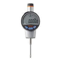
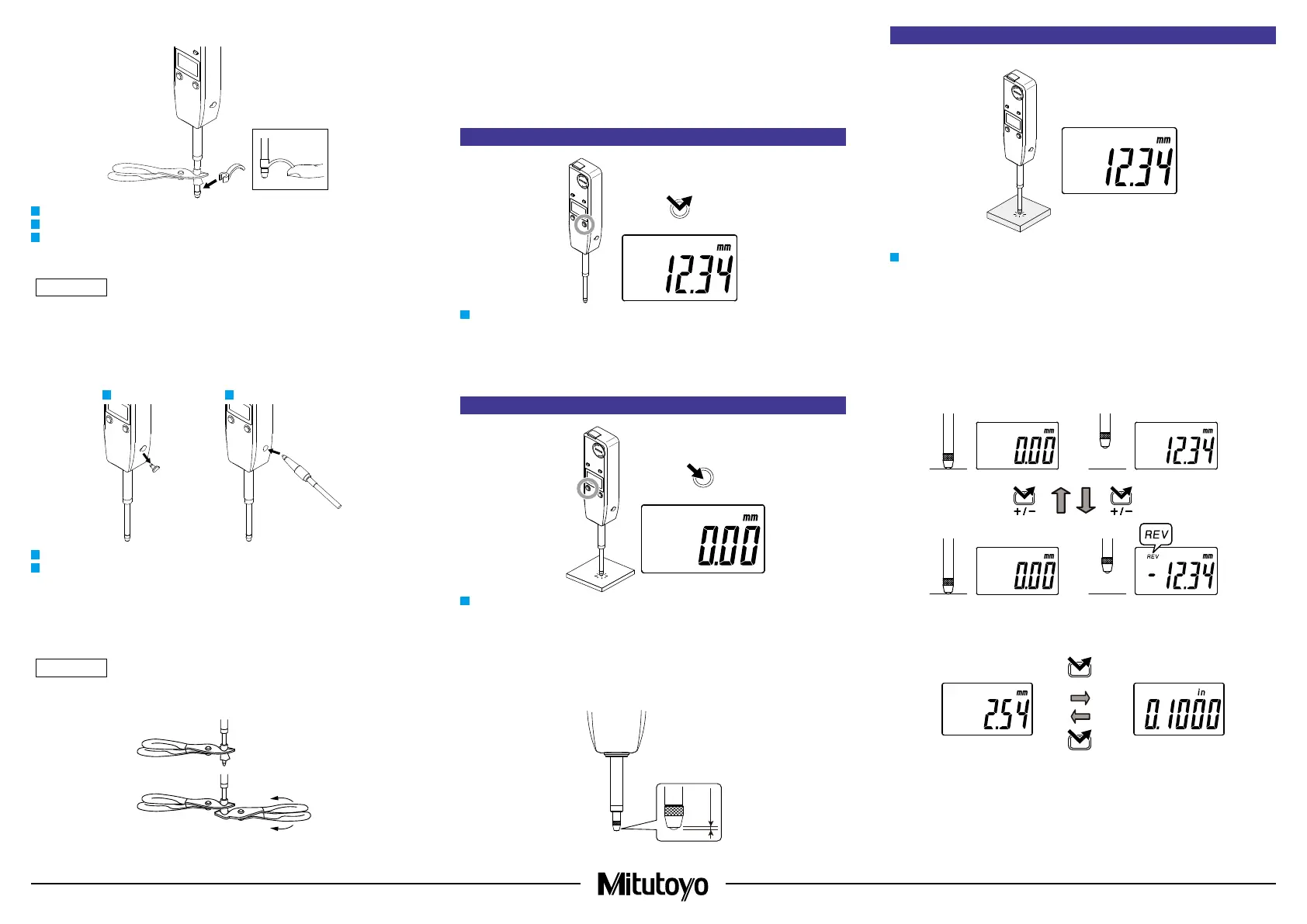
4. Power ON/OFF
ON/OFF
1
Press the [ON/OFF] key to turn the product on and off.
Tips
• If the power does not turn on even when the [ON/OFF] key is pressed, the battery may be
depleted. Replace the battery.
•
Even after the power is turned off, the reference point set and counting direction will be retained.
5. ORIGIN Setting (Reference Point Setting)
Master
1
Move the spindle to the point to be set as the reference point, and then press the [ORIGIN] key
for 1 second or more.
⇨ The indicated value becomes 0.00 and the reference point (ORIGIN) is set.
Tips
•
Place the contact point on the workpiece several times to verify that the measured value is stable.
• This product does not guarantee stable repeatability within 0.2 mm from the bottom dead
center (when the spindle is completely extended). When performing reference point setting, be
sure to lift the spindle at least 0.2 mm above the bottom dead center.
•
A rubber damper is attached to this product to soften the spindle impact. Although the indicated value
may not be stable at the bottom dead center due to the elasticity of the damper, this is not a malfunction.
6. Measurement Method
1) Measurement
1
Gradually and lightly place the contact point on the workpiece in the same orientation and
conditions as for reference point setting, and then read the indicated value.
Tips
If the contact point strikes the workpiece hard, the workpiece may deform and measurement re-
sults may be affected.
2) Switching counting direction
The counting direction can be changed by pressing the [+/-] key. If the product is set to negative
counting when the spindle is pushed in, [REV] is shown on the top left of the LCD.
3) Switching units
Press the [in/mm] key to switch the unit between in (inches) and mm (millimeters).
in/mm
in/mm
● Positive count
Measurement workpiece
● Negative count