Printed in Japan
Mitutoyo Corporation 1-20-1 Sakado, Takatsu-ku, Kawasaki City, Kanagawa 213-8533
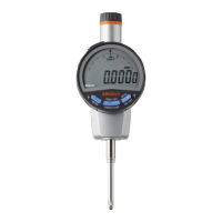
3. Setup
1) When used facing up
The product can be used in orientations up until the contact point becomes horizontal. The spindle
will not return to the reference point, so when using the product with the contact point facing
upward, replace the internal coil spring with a reverse orientation coil spring (optional).
Part No. 02ACA571 (25.4 mm stroke model)
Part No. 02ACA773 (50.8 mm stroke model)
B
A
2
1 4
3
1
Remove the five screws on the back using a #0 Phillips screwdriver, and then remove the back.
2
Use tweezers or the like to pinch the spring attachment hooks in the order of (A) and (B), and
then remove the coil spring.
3
Attach the new coil spring to the spring attachment pins in the order of (B) and (A).
4
Attach the back by tightening the five screws on the back using a #0 Phillips screwdriver.
Tips
・ Do not forcibly pull the removed coil spring by hand.
・ Using the product with the contact point facing downward with a reverse orientation coil spring
installed will cause the measuring force in the specifications to increase.
・ Store the removed coil spring to prevent loss.
2) Mounting to a stand, jig, etc.
• Whenever possible, avoid fixing the stem directly with a set screw, etc.
• The spindle may not be able to move smoothly if the screw is tightened with a tightening torque
of 300 cN・m or more to secure the stem.
ø8
+0.02
+0.005
ø9.52 (3/8 in)
+0.02
+0.005
mm
Stem
Tips
When mounting the product to a stand or jig, use the stem or a back with lug (optional). If using
the stem, use a slotted holder with a ø8 mm hole (ISO/JIS type) or ø9.52 mm hole (AGD type)
with G7 (+0.005 to +0.02 mm).
3) Mounting the back (optional)
Various backs (optional) for dial gage can be used to secure the product.
1
Remove the four screws (excluding (A)) on the flat back.
2
Line the optional back up with the flat back, and then fix it using the screws that were removed
in step
1
.
(A)
4) Mounting the lifting lever
1
Fix the spindle, using pliers padded with a rag, etc., from the opposite side so that it does not turn.
2
Insert the lifting lever into the spindle.
3
Rotate the lifting lever to adjust the orientation.
5) Mounting the lifting knob (optional)
Part No. 21EZA197 (25.4 mm stroke model)
Part No. 21EZA200 (50.8 mm stroke model)
• Using the product while the lifting knob is not secured firmly may damage internal components or
the workpiece.
• Dust, mist, or other substances could enter the gap between the spindle and main body, causing
malfunction or failure. Avoid using the product in very dusty or misty environments.
1
Rotate the cap counterclockwise to remove it from
the product.
2
Fix the spindle, using pliers padded with a rag, etc., so
that it does not turn, and then insert the lifting knob to
the screw (M2.5) on the upper edge of the spindle.
During this process, push the spindle upward.
3
Turn the cap on the lifting knob to fix it to the upper
edge of the bushing.
Tips
Store the removed cap to prevent loss.
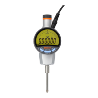
6) Mounting the release (optional: part No. 540774)
• Always mount the rubber cap if a release is not mounted.
• The rubber cap is a screw-in type.
• The product may be damaged if an item other than the release is inserted or if excessive force
to push in is applied.
• Raising or lowering the spindle with the release while the release is not secured firmly may
damage the internal components or the workpiece.
1
Remove the rubber cap from the release mounting hole.
2
Screw the release firmly into the hole.
Tips
• Store the removed rubber cap to prevent loss.
・ The spindle can be moved a maximum of 25.4 mm
with the release.
7) Contact point replacement
When replacing the contact point, turn the contact point while fixing the spindle. Otherwise, the
product may be damaged.
Mount and remove the contact point with a rag and 2 pairs of pliers (one for fixing the spindle) as
shown in the figure.
Tips
• Changing the contact point may cause changes in external dimensions and measuring force, or
restrictions on the possible measurement directions.
• Errors due to the contact point (perpendicularity of flat contact point, center runout of roller
contact point, etc.) are added to the measurement accuracy.
•
Various contact points are available as options. Refer to the Measuring Instruments Catalog for
details.
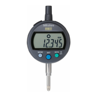
4. Display Angle Adjustment
• Do not rotate beyond the stoppers at (A) and (B)
positions. This may cause damage.
• Do not pull or push the display. This may cause
damage.
The display can rotate up to 240° (A) clockwise or 90°
(B) counterclockwise from the initial position.
Adjust it to an angle from which it can be easily read.
2
1
Release
Rubber cap
(A)
(B)
Flat back
1
2
3
Lifting knob
Cap
Upper edge of
bushing
Cap

 Loading...