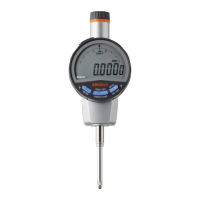
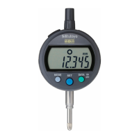
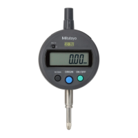
Printed in Japan
Mitutoyo Corporation 1-20-1 Sakado, Takatsu-ku, Kawasaki City, Kanagawa 213-8533
3) Holding the displayed value (if not connected to an external device)
The displayed value can be held (fixed).
1
Press the [DATA] key.
⇨ [H] will appear and the displayed value will be held (the displayed value will be retained even
if the workpiece is removed).
2
Press the [DATA] key while the displayed value is held.
⇨ [H] will go out and the held displayed value will be released.
1 2
Tips
During tolerance judgment enlarged display, the Hold function will not work even if the [DATA] key
is pressed.
Refer to "10.2) Setting Tolerance Judgment function" for details on the tolerance judgment
enlarged display.
4) Externally outputting the displayed value (if connected to an external device)
This function is enabled only when connected to an external device. The display value is output to
the connected external device.
1
Press the [DATA] key during measurement mode.
⇨ The displayed value is output to the connected external device.
Tips
• Refer to "13. Output Function" for details on installing connection cables, pin assignments,
output data format, and timing chart.
• Carefully read the User's Manual of the data processing device to be connected when using the
External Output function.
• If inputting an output request (REQ) from the connected external device, do so only when the
spindle is stopped. If an output request (REQ) is received while the spindle is operating, it may
output an incorrect value or data output may not be possible.
• If output requests (REQ) are received over short intervals, data output may not be possible.
• Data output using the [DATA] key is not possible during tolerance judgment enlarged display.
The measured value is externally output only when an output request (REQ) from an external
device is received.
1
Connection cable
Outputs 10.015 mm
10. Setting Parameters
There are five types of parameter items to set.
1) Counting direction
4) Calculation
function
2) Tolerance Judgment
function
5) Function lock 3) Resolution
Tips
• Press and hold the [MODE] key to cancel the parameter setting. Note that unconfirmed settings
will not be reflected.
• All parameter settings are retained even when the power is turned off. However, they are
cleared when replacing the battery and must be reset.
1) Setting counting direction
The counting direction can be set with regard to the spindle movement direction.
Positive count
Negative count
1
Press and hold the [MODE] key to enter parameter setting mode.
⇨ Shifts to parameter setting mode.
2
Selecting the parameter item to set
1 Confirm that [dir.] is blinking.
2 Press the [SET] key.
⇨ Counting direction can be set.
3
Setting the counting direction
1 Press the [MODE] key to select the counting direction.
[▼] off: Counts up when the spindle is raised.
[▼] blinking: Counts down when the spindle is raised.
Each time the [MODE] key is pressed, it will switch the
counting direction between up and down.
2 Press the [SET] key.
⇨ Settings are confirmed; shifts to next parameter item.
( Proceed to step
3
in "2) Setting Tolerance Judgment
function".)
1
2 -1
2 -2
3 -2
3 -1
2) Setting Tolerance Judgment function
The tolerance values can be set to provide a GO/NG judgment
(pass/fail judgment) for the measured value. Tolerance values
can be set independently for ABS/INC measurement systems
and normal/calculation measurement (total of 4 types).
-NG
-NG
OK
OK
+NG
+NG
Normal display
(measured value
and judgment
result)
Enlarged display
(judgment result only)
1
Confirm that the measurement mode to which the
tolerance judgment function is applied is selected.
⇨ Refer to "4) Setting Calculation function" for
information on how to switch between normal/
calculation measurement.
2
Press and hold the [MODE] key to enter parameter
setting mode.
⇨ Shifts to parameter setting mode.
3
Selecting the parameter item to set
1 Press the [MODE] key until [toL.] is displayed.
2 Press the [SET] key.
⇨ Tolerance Judgment function can be set.
4
Setting the measurement result display method
1 Select display method by pressing the [MODE]
key.
⇨ Each time the [MODE] key is pressed, it will
switch display methods in the order of
"A→B→C→A."
A: Display off
B: Normal display
C: Enlarged display
2 Press the [SET] key.
⇨ Selection is confirmed.
If "Normal display" or "Enlarged display" was
selected:
[▶] blinks and the upper limit can be set.
To skip setting the upper limit, press the
[SET] key again (proceed to step
6
).
If [oFF] was selected:
0.001 mm models
Proceed to step
2
in "3) Switching resolution".
0.01 mm models
Proceed to step
2
in "4) Setting Calculation
function".
Key icon operation
=
> 2 s
=
< 1 s
2
3 -1
3 -2
4 -2
4 -2
4 -1
A
B
C
 Loading...


