Do you have a question about the Mitutoyo ID-H0530 and is the answer not in the manual?
Warns about improper use of the AC adapter and power supply, which could lead to injury or death.
Advises on safe disposal of the instrument, noting the presence of liquid crystal.
Lists actions and conditions that can cause instrument failure, emphasizing careful handling.
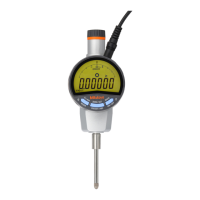
Identifies and illustrates the main components of the Digimatic indicator and accessories.
Explains the various symbols and indicators displayed on the LCD unit of the instrument.
Instructions on how to attach the clamp filter (ferrite core) to the AC adapter cord.
Guidance on securely mounting the indicator on a stand or jig using its stem.
Steps for attaching the lifting lever to the spindle of the Digimatic indicator.
Details on how to attach the release mechanism (option) to the instrument.
Instructions for mounting a back with a lug or other special backs onto the indicator.
Procedures for detaching and attaching different contact points to the indicator's spindle.
Steps for connecting the power supply and starting or stopping the operation of the Digimatic indicator.
Explains how to enter and navigate the parameter setup mode to change settings like resolution and direction.
Guide on how to switch between inch and millimeter unit systems in the parameter setup.
Instructions for changing the digital resolution of the indicator in the parameter setup.
How to select and set the analog range or resolution for the instrument.
Procedure for changing the count direction (+ or -) of the measurement display.
Guide to selecting the data output format (SPC or RS-232).
Details on configuring RS-232 communication settings like baud rate and parity.
Instructions for setting the ID number for RS-232 and remote control operations.
How to switch between INC and preset systems for length measurement.
Procedure to reset all instrument parameters to their factory default settings.
Information on entering and operating the instrument in different measurement modes.
How to set the INC or Preset system and establish a reference point for measurement.
Explains how to perform a zero set in the INC measurement system.
Guide on setting a specific preset value for measurements in the Preset system.
How to switch between different measurement types like Normal, Tolerance, and Peak Hold.
Detailed steps for setting and checking upper and lower limit values for tolerance judgment.
Procedure for performing run-out peak hold measurement to capture the total indicator reading.
Instructions for capturing and holding the maximum value during measurement.
Guide on how to capture and hold the minimum value during measurement.
How to output measurement data to an external device or hold the data.
Instructions for enabling and disabling the function lock to prevent accidental key presses.
Procedure to center the analog display pointer for accurate readings.
How to connect and use the instrument for data transfer using the SPC (Digimatic) method.
Steps for connecting the instrument for SPC data output, including setup mode.
Details the pin assignment and circuit diagram for the I/O connector used for data communication.
Describes the format of the data outputted via SPC (Digimatic) connection.
Illustrates the timing sequence for data transfer signals in SPC communication.
How to connect and use the instrument for data transfer via RS-232 communication.
Steps for connecting the instrument for RS-232 data output, including parameter setup.
Details the pin assignment for the D-sub 9-pin connector used for RS-232 communication.
Lists the technical specifications for RS-232 communication, such as baud rate and parity.
Outlines the commands for controlling the instrument and receiving data via RS-232.
Provides an example of RS-232 communication using hyper terminal for setting up the instrument.
Lists common error messages, their definitions, and corrective actions for normal operation.
Details the technical specifications of the Digimatic indicator models, including range, accuracy, and power.
Lists the standard accessories included with the Digimatic indicator.
Lists various optional accessories available for the Digimatic indicator.
| Model | ID-H0530 |
|---|---|
| Category | Measuring Instruments |
| Type | Digital Indicator |
| Display | LCD |
| Measuring Force | 1.5 N or less |
| Operating Temperature | 0 to 40 °C |
| Storage Temperature | -10 to 60 °C |
| Measuring Range | 0-12.7mm (0-0.5") |
| Resolution | 0.001mm (0.00005") |
| Accuracy | ±0.003mm (±0.0001") |
| Data Output | Yes |
| Power Supply | SR44 (silver oxide battery) x 1 |
| Weight | Approx. 120 g |