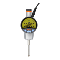
No. 99MAH016B
Contents
FOREWORD ....................................................................................................................................................... i
PRECAITIONS .................................................................................................................................................... i
WARRANTY ....................................................................................................................................................... ii
NOTES ON OVERSEAS TRANSFER ............................................................................................................... ii
1 NAME OF RACH PART ......................................................................................................................... 1-1
1.1 Part Names of the Main Unit ........................................................................................................ 1-1
1.2 Details of the LCD Unit ................................................................................................................. 1-2
2 INSTALLATION ...................................................................................................................................... 2-1
2.1 Attaching the Clamp Filter............................................................................................................ 2-1
2.2 Mounting on a Stand or a Jig ....................................................................................................... 2-1
2.2 Attaching the Lifting Lever ........................................................................................................... 2-1
2.3 Attaching the Release ................................................................................................................... 2-2
2.4 Mounting the Lug or Special Back .............................................................................................. 2-2
2.5 Replacing the Contact Point ........................................................................................................ 2-2
3 OPERATING PROCEDURE .................................................................................................................. 3-1
3.1 Starting/Stopping This Instrument .............................................................................................. 3-1
3.1.1 Connecting to the power supply .......................................................................................... 3-1
3.1.2 Start / Stop .............................................................................................................................. 3-1
3.2 Parameter Setup Mode ................................................................................................................. 3-1
3.2.1 Switching the unit system between inch and mm during display of “unit” (only in inch spec) .... 3-2
3.2.2 Switching the digital resolution during display of “res.” .................................................. 3-2
3.2.3 Switching the analog range (analog resolution) during display of “range” .................... 3-3
3.2.4 Switching the count direction during display of “dir” ....................................................... 3-3
3.2.5 Switching the I/O format between SPC(Digimatic) and RS-232 during display of “output” ......... 3-3
3.2.5.1 RS-232 setup .................................................................................................................... 3-3
3.2.6 Setting ID No. for RS-232 communication and remote control during display of “id” .. 3-4
3.2.7 Switching the length measuring system during display of “start” .................................. 3-4
3.2.8 Returning all parameters to factory defaults during display of “reset” .......................... 3-4
3.3 Measurement Mode ....................................................................................................................... 3-5
3.3.1 Setting the length measuring system and reference point ............................................... 3-5
3.3.1.1 INC system (Zero set) ...................................................................................................... 3-5
3.3.1.2 Preset system (setting the preset value) .......................................................................... 3-5
3.3.2 Switching a measurement type in the measurement mode .............................................. 3-6
3.3.2.1 Tolerance judgment (setting/checking the upper and lower limit values) ......................... 3-6
3.3.2.2 Run-out peak hold during display of “TIR” ....................................................................... 3-7
3.3.2.3 Maximum value peak hold during display of “Max” .......................................................... 3-7
3.3.2.4 Minimum value peak hold during display of “Min” ............................................................ 3-8
3.3.3 Data output / Data hold ......................................................................................................... 3-9
 Loading...

