4 DATA I/O
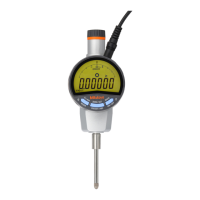
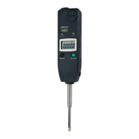
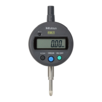
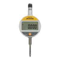
Using the M-SPC cable (sold separately), the instrument can be connected to the DP-1VR
Digimatic Mini-processor or similar data processors, to transfer, total and record measurement
values.
Remove the output connector cover and insert the cable securely. (Place the cover in a
bag and store it in a safe place).
4.1 OutputConnector
19
10 2
DATA or CK
*1
REQ
*2
CMOS
5V
22k
1k
Ω
0.01µF
PIN# Signal I/O
1. GND -
2. *1 DATA1 OUT
3. *1
C
OUT
4. N.C -
5. *2
RE
IN
6. *3
ENTRY
IN
7. *3
DATA2
IN
8. +9V -
9. +9V -
10. GND -
*3 : ENTRY
and DATA2 are exclusive connector for the Presetter.
4.2 OutputDataFormat(DATA1)
d1 d2 d3 d4 d5 d6 d7 d8 d9 d10 d11 d12 d13
All ”F”(1111)
Measurement value Unit
Sign
+:0(0000)
-:8(0001)
Decimal position
0.0.0.0.0.0
↑↑↑↑↑
5 4 3 2 1
mm 0(0000)
inch 1(1000)
mm,GO 2(0100)
mm,+NG 3(1100)
mm,-NG 4(0010)
inch,GO 5(1010)
inch,+NG 6(0110)
inch,-NG 7(1110)
For example., In case of output data as ”-2.471mm”.
1111 1111 1111 1111 0001 0000 0000 0100 0010 1110 1000 1100 0000
F F F F 8 0 0 2 4 7 1 3 0
MANUAL No.99MAH001B2
-11-
 Loading...
