Mitutoyo Corporation 1-20-1 Sakado, Takatsu-ku, Kawasaki City, Kanagawa 213-8533
Date of publication: February 1, 2022
Printed in Japan
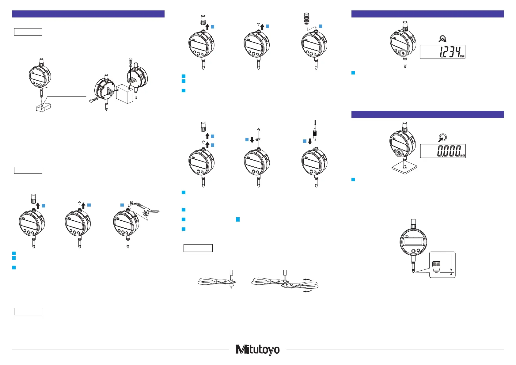
3. Setup
1) Mounting to a stand, jig, etc.
• Whenever possible, avoid xing the stem directly with a set screw, etc.
• The plunger may not be able to move smoothly if the screw is tightened with a tightening torque
of 150 cN•m or more to secure the stem.
ø
8* +0.02/+0.005 mm
*ADG type:
ø
9.52 (0.375 in)
Tips
When mounting the product to a stand or jig, use the stem or lug on the back. If using the stem,
use a slotted holder with a ø8 mm or ø9.52 mm hole with G7 (+0.005 mm to +0.02 mm).
2) Mounting the lifting lever
(Options: Part No. 21EZA198)
•
Using the product while the stop screw is not secured rmly may damage internal components or the workpiece.
• If not mounting a stop screw, always mount the original screw on the plunger top end.
Otherwise internal components or the workpiece may be damaged.
1
2 3
1
Rotate the cap counterclockwise to remove it from the product.
2
Fix the plunger, using pliers padded with a rag, etc., so that it does not turn, and then remove
the screw (M2.5 at the top end of the plunger.
3
Mount the stop screw supplied with the lifting lever and, with the lever tip caught by the stop
screw, mount the lifting lever on the lifting lever mount (dovetail).
Tips
Store the removed screw and cap to prevent loss.
3) Mounting the lifting knob
(Options: Part No. 21EZA105)
•
Using the product while the lifting knob is not secured rmly may damage internal components or the workpiece.
• If not mounting a lifting knob, always mount the original screw on the plunger top end.
Otherwise internal components or the workpiece may be damaged.
1
2 3
1
Rotate the cap counterclockwise to remove it from the product.
2
Fix the plunger, using pliers padded with a rag, etc., so that it does not turn, and then remove
the screw (M2.5) at the top end of the plunger.
3
Mount the lifting knob on the top end of the plunger.
Tips
Store the removed screw and cap to prevent loss.
4) Mounting the release (Optional part No. 21JZA295)
2
1
3
4
1
Rotate the cap counterclockwise to remove it from the product.
Tips
Store the removed screw and rubber cap to prevent loss.
2
Fix the plunger, using pliers padded with a rag, etc., so that it does not turn, and then remove
the screw (M2.5) on top of the plunger.
3
Use the screw removed in step
2
to secure the mounting plate supplied
with the release to the plunger.
4
Screw the release rmly into the hole.
5) Contact point replacement
When replacing the contact point, turn the contact point while xing the plunger. Otherwise, the
product may be damaged.
Mount and remove the contact point with a rag and 2 pairs of pliers (one for xing the plunger) as
shown in the gure.
Tips
• Changing the contact point may cause changes in external dimensions and measurement
force, or restrictions on measurement directions.
• Errors due to the contact point (perpendicularity of at contact point, center runout of roller con
-
tact point, etc.) are added to the measurement accuracy.
• Various contact points are available as options. Refer to the Mitutoyo MEASURING INSTRU
-
MENTS CATALOG for details.
4. Power ON/OFF
ON/OFF
1
Press the [ON/OFF] key to turn the product on and o.
Tips
• If the power does not turn on even when the [ON/OFF] key is pressed, the battery may be
dead. Replace the battery.
• Although the plunger may feel heavy at the bottom dead center when using for the rst time,
this can be resolved by pushing the plunger up once.
•
Even after the power is turned o, the reference point set and counting direction will be retained.
5. ORIGIN Setting (Reference Point Setting)
Master
ORIGIN
1
Move the plunger to the point to be set as the reference point, and then press the [ORIGIN] key
for 1 second or more.
⇨
The indicated value becomes zero and the reference point (ORIGIN) is set.
Tips
• Place the contact point on the workpiece several times to verify that the measured value is stable.
• This product does not guarantee stable repeatability within 0.2 mm from the bottom dead
center (when the plunger is completely extended). When performing reference point setting, be
sure to lift the plunger at least 0.2 mm above the bottom dead center.
0.2 mm
• A rubber damper is attached to this product to soften the plunger impact. Although the indicated
value may not be stable at the bottom dead center due to the elasticity of the damper, this is
not a malfunction.
Stem
2

 Loading...