Chapter Two: Installation Electrical Information
27
Interface Connector
The 15-pin Type “D” male Interface connector, located on the front of the unit, provides access
to the power and signal input pins.
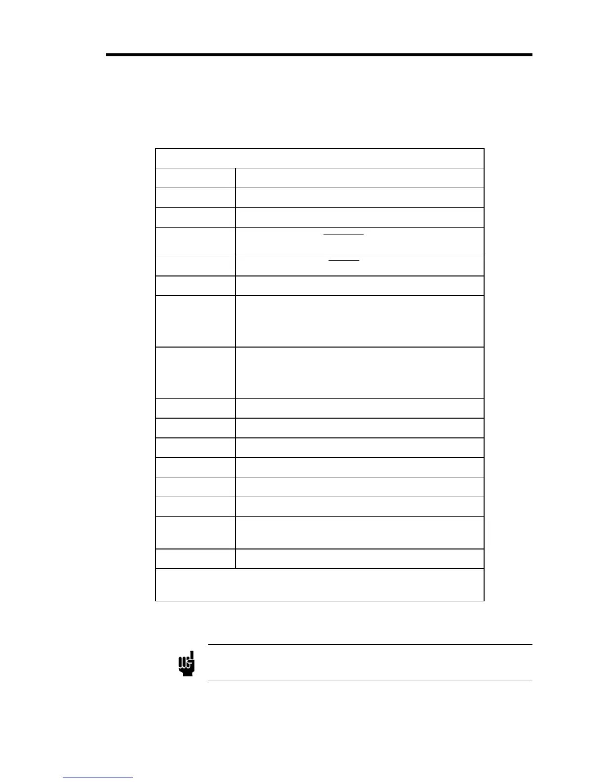
Interface Connector Pinout
Pin Number Assignment
1 Valve Test Point
2 + Voltage or Current Input
3
CLOSE
Input*
4
OPEN
Input*
5 Power Common (±15 VDC Input)
6 Power Common (+24 VDC Input)
or
-15 VDC for the ±15 VDC supply
7 24 VDC for +24 VDC supply
or
+15 VDC for the ±15 VDC supply
8 No Connection
9 No Connection
10 No Connection
11 No Connection
12 - Voltage or Current Input
13 No Connection
14 +5 VDC Input for TTL Open or Close compatible
logic*
15 Chassis
*
The valve position refers to the a normally closed valve. The action
will be reversed on a normally open valve.
Table 6: Interface Connector Pinout
Note
The “No Connection” pin assignment refers to a pin with no internal
connection.