Chapter Three: Overview On-Board Jum
ers
33
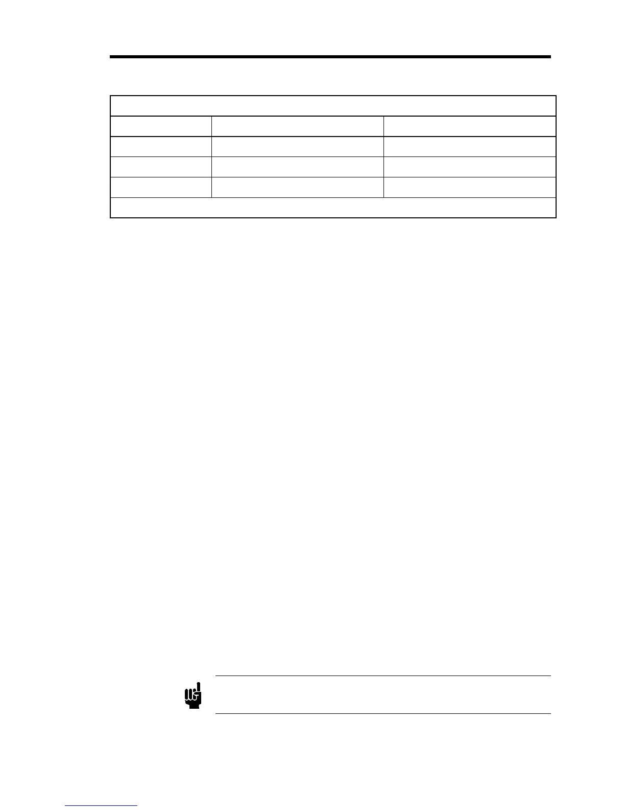
Jumper Assignments
Jumper Assignment Options
J3 Input Type Voltage* or Current
J4 Full Scale Voltage 0 to 5 V* or 0 to 10 V
J5 Digital Input Control TTL or Open Collector*
* Factory default setting.
Table 9: Jumper Assignments
Jumper J3 - Input Type
The position of jumper J3 determines whether the input will be a voltage or current. Place the
jumper over the position labeled “VIN” for voltage input, or over the position labeled “4 - 20”
for current input. The unit is configured at the factory for voltage input (“VIN”).
Jumper J4 - Full Scale Voltage
The position of jumper J4 determines the full scale (FS) setting for the voltage input, either
5 VDC or 10 VDC. The unit is configured at the factory for 0 to 5 V full scale voltage.
Place the jumper over the position labeled “0 – 5 V” for 5 VDC FS voltage input, or over the
position labeled “0 – 10 V” for 10 VDC FS voltage input.
The current input must always be a 4 to 20 mA signal. The input impedance for the 4 to 20 mA
input is 250 ohms. To configure the unit for current input, set jumper J3 for current input and
position the jumper on J4 for 0 to 5 V.
Jumper J5 - Digital Input Control
The position of jumper J5 sets the type of control for the digital input signals, either TTL
compatible logic or Open Collector. Place the jumper over the position labeled “5 VDC” for
TTL compatible logic, or over the position labeled “OPEN COL” for Open Collector control.
The unit is configured at the factory for open collector control (“OPEN COL”).
To configure the unit for TTL compatible logic, place the J5 jumper in the 5 VDC position and
connect a 5 VDC supply to pin 14 on the Interface connector (refer to Table 6, page 27). The
inputs are pulled-up to the supply with 10K ohms. The OPEN and CLOSE pins are activated by
a TTL low
≤
0.8 VDC sinking a minimum of 1.6 mA.
To configure the unit for Open Collector control, place the jumper on J5 to the “OPEN COL”
position. The OPEN and CLOSE pins are activated by an open collector (or switch) low
≤
0.8
VDC sinking a minimum of 4 mA.
Note
When using Open Collector control, the leakage current on the output
must not exceed 200
µ
A when in the high state.