page 4 of 16 File: SG1024_r1eng - April 2017 - Technical note: SG 1024
PM 250
SG 1024 Solid State Microwave Generator
Handling Warnings
The SG 1024 has two handles on the front panel to help
unpacking and handling operations: never use only the
handles to lift the equipment but support the weight with
an appropriate base on bottom!
The handles do not withstand the off-center weight of the
equipment ( kg 22.5= 49.5 lbs).
General Description
The SG1024 is a solid state generator able to provide up to
1000 W at the frequency of 2450 MHZ (2.45 GHz) and is
powered through a wide input AC/DC power supply with
input range from 180 to 250 Vac, including PFC module.
The output power can be adjusted continuously, from 2%
up to 100%, using an external analog signal from 0.2 to
10Vdc,orbyremotecontrolthrougheldbusinterfaceorby
manual commands (depending from equipment version: see
next table).
The generator offers the capability to adjust the output
frequency over a total range of +/- 50 MHz with respect the
nominal frequency of 2450 MHz, with step 1 MHz.
The SG1024 is built in a water cooled 19” wide rack, 2 HE
high, with a front panel including a graphic display: the rear
panelcarriesconnectorsforaneasyset-upandwaterttings
of the quick-coupling type.
The SG 1024 is offered in two versions:
- the “Display” version with front panel manual commands
and PLC interface to control by I/O: it carries also one USB
standard port, which allows to drive/read data from the unit
with a simple software (like our “Front Panel” software distri-
buted freely).
- the “Bus” version (vers. 1) which has an industrial
bus interface Powerlink or Modbus/TCP allowing
connection of multiple devices on the same bus.
SG 1024 Versions Overview
MODEL ABBREV. BUS DISPLAY
Version no. 1 2
External Control (PLC) possible possible
LED Panel Indicators n.a. n.a.
Local Commands (Manual) possible
Graphic Interface
Network Control
n.a.
USB Control (possible, not a default set-
ting)
n.a.
Frequency control (ISM band range)
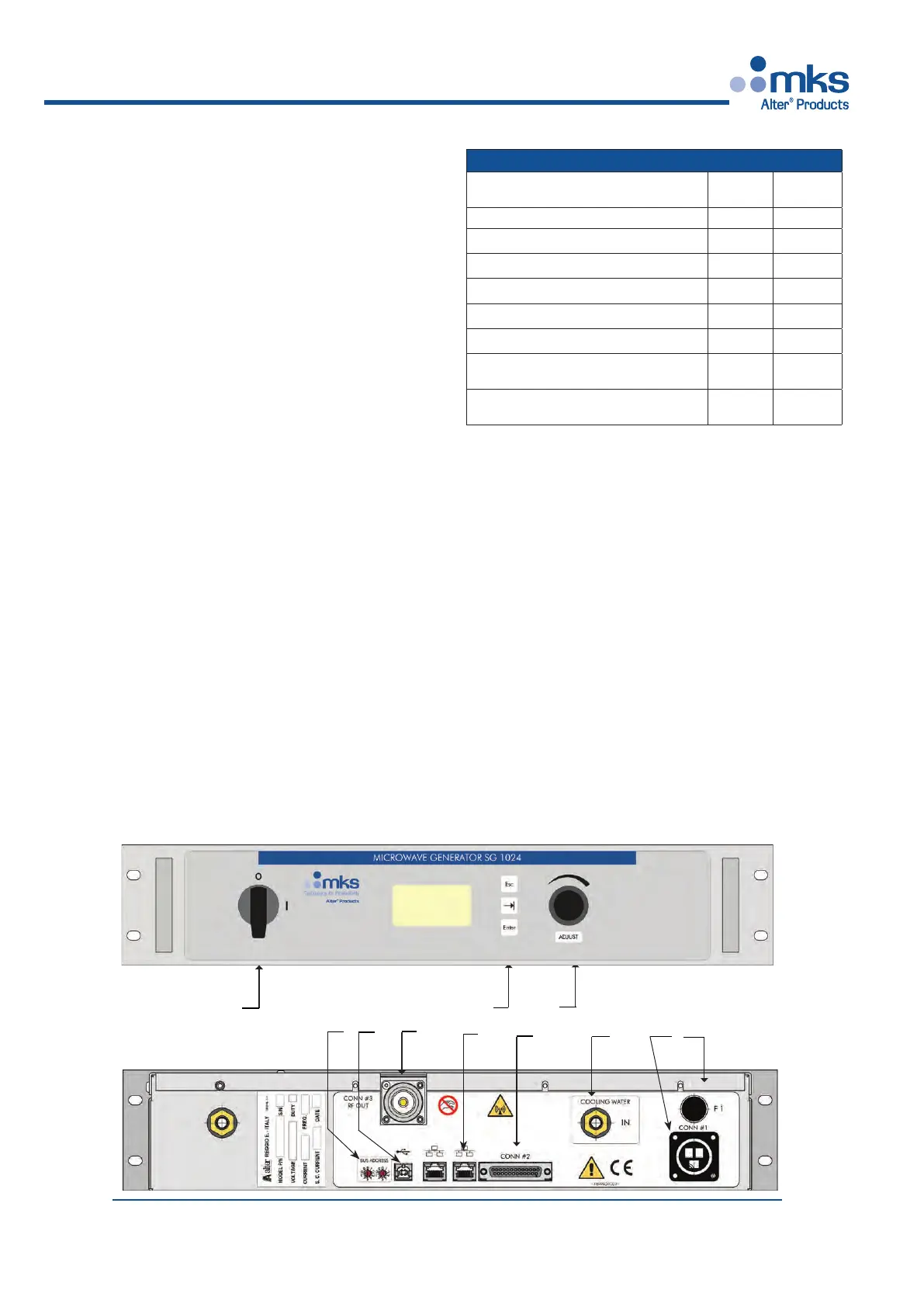
Front and Rear Panel Layout
(In the following descriptions the numbers in brackets [ n ] refer to
numbers in the annexed drawing).
The front panel of version 2 “Display” contains:
- Main Switch 0-1 [1]
- the User interface: Graphic Display, three push-buttons [2]
and a rotaing knob [3]
ESC allows moving from one page to another,
TAB (the button with the arrow) to scroll down the selection,
ENTERtoconrmtheselection.
Knob allows to modify a value when this is enabled.
- a standard USB port [4]
For a detailed description see the chapter “Manual Com-
mands” on next pages.
The manual commands are active only when the related
option is enabled: if it is not selected, then the unit can run
only with External commands.
2
4
3
8
1
Front
View
Rear
View
9
7
5
6
10
11
 Loading...