File: SG1024_r1eng - April 2017 - Technical note: SG 1024 page 5 of 16
PM 250
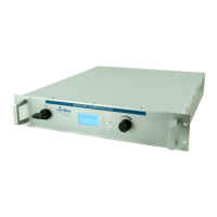
SG 1024
The rear panel comprises the followings:
- two fuse sockets (F1) [4]
- 3 pins socket for line input (CONN #1, male) [5]
- water connector quick-lock IN [6] and OUT
- 25 pins “D” socket for I/O signals (CONN #2, female) [7]
- a 7/16 Socket for RF output (CONN #3, female) [8]
- a standard USB port [9]
-adoubleRJ45socketforeldbusversion(enabledonlyon
Vers.1) [10]
- the BUS address switches (enabled only on Version 1) [11]
Equipment installation
The equipment cannot operate cantilevered, it must be put on
abenchorxedinsideacabinetbymeansofscrewsonthe
front panel (which is provided with 4 holes) and supported by
means of a proper frame on the bottom for, at least, 3/4 of the
total depth.
Handling instructions
The equipment weight is 22.5 kg (49.5 lbs). Always lift from
the bottom and use a rugged support to avoid personal injury
and damage to equipment itself.
In case of shipping, package with the original package or use
SG 1024 Ratings & Specications
Description Units Value Function Note
Line input range
Input Current, max:
V
ac
A
rms
180 ÷ 250
12
Power input, 50/60Hz
@230V input, full power
CONN #1, pin 1-2, ground pin 3
See wiring schematic
Transient Overvoltage Cat. II According IEC 664
Output power, max W
rf
1000 Microwave power, range 2400-
2500 MHz
± 3% in matched condition
± 10% in unmatched condition
Electrical efciency (Out/In) Ref. 100% 36% Ref. 50% --> efciency 26%
Output power range: W
rf
50 ÷ 1000 Adjustable range 2÷100% Max value differs at frequency band
limit
Output linearity: W
rf
± 20 Forward power (Displayed value vs
monitor signal)
Output stability: 1% For input uctuations within ±10%
Output frequency, nominal:
range:
MHz
MHz
2450
±50
ISM band 2400÷2500 Adjustable by user, step = 1 MHz
Enabling signal, digital input: V
dc
+24
Range 8÷30
ON/OFF output & alarm reset
Input Z: 10 kOhm
CONN #2, pin 4. To reset alarm hold
OFF for 2 seconds
Response time to full power (0-100%):
Response time to half power (0-50%):
msec
10
5
Pulsing capability
Time calculated on the external
Enable signal
Response time to switch OFF: msec 1 Using Enabling signal
Switch OFF time for alarm msec 3 Automatic shut-off
Reference signal, analog input: V
dc
0.2÷10 Power control 2÷100% CONN #2, pin 5. Ground pin 18
Input Z=50 kOhm
Alarm contact, general:
Contact rating: max voltage
max current:
V
mA
30
500
OPEN: Alarm state or powe OFF
CLOSED: OK
CONN #2, pin 1-4
Alarm code, 4 bit contacts (0/1)
Contact rating: max voltage
max current
V
mA
30
100
Inform type of alarm with emis-
sion of 4 bit code
See relevant table
CONN #2, pin 8-21-9-22 (bit 0...3)
Common pin 13
Ready contact rating: max voltage
max current
V
mA
30
500
CLOSED when is ready
OPEN not ready or Alarm state
CONN #2, pin 24-12
Interlock input: V
dc
24 0: Alarm, shut OFF outputs.
+24V: OK
CONN #2, pin 10-23
Monitor signals, analog outputs (2): V
dc
0÷10 TBD CONN #2, pin 2-15 (1); pin 3-16 (2)
Designed for receiver impedance
>30 kOhm (for accuracy <1%)
Voltage output (internal generator) V
dc
+24 Auxiliary voltage generator, regu-
lated, for user interface
CONN #2, pin 20.
Max current: 100 mA