Zeus200 Installation manual
V 1.0.7 - 12/10/2020 Page 17 of 28
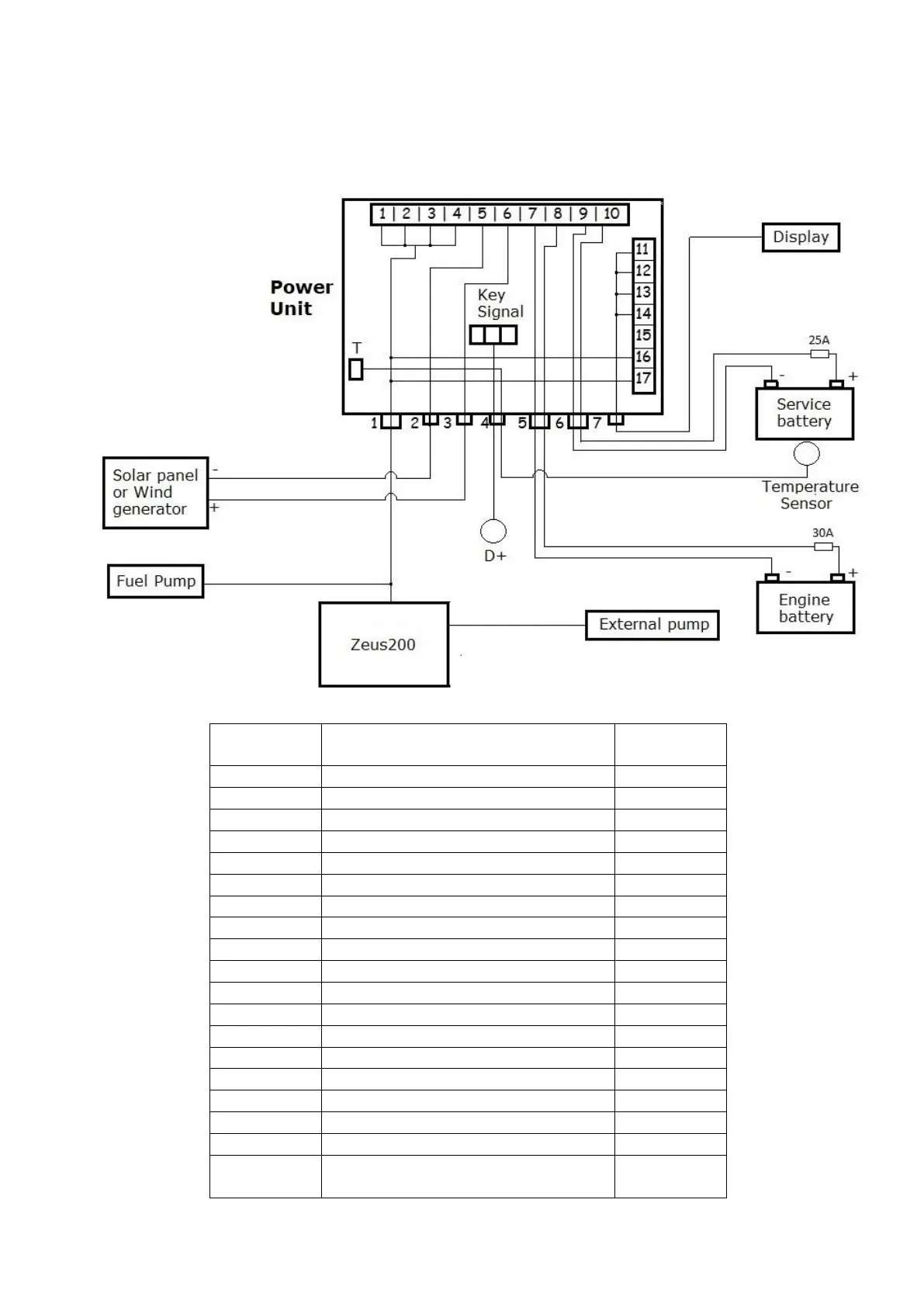
2.5.3 Electrical diagram
The following figure shows the wiring diagram, with the numbering of the terminals inside the control
unit and the number of cable entries to be used for the needed connections.
Generator – Black wire 6mm
Generator – Brown wire 4mm
Generator – Green wire 4mm
Sola panel (opt.) – Negative
Solar panel (opt.) – Positive
Engine battery (opt.) – Negative
Engine battery (opt.) – Positive
Services battery – Negative
Services battery – Positive
Display Unit – Yellow wire
Display Unit – Green wire
Display Unit – Brown wire
Display Unit – White wire
Generator – Black or cyan wire 0.5mm
Generator – Red or white wire 0.5mm