Page 27
q Install the Z-Bend in each of the two Z-Bend couplers into the hole in the
servo arms that you enlarged, then attach the cables to the Z-Bend couplers,
using the same techniques that you used to install the elevator cables to the
Z-Bend couplers.
IMPORTANT Make sure that both lengths of cable are pulled tight. There
should not be any slack in the cables. Also remember to apply a couple of
drops of thin C/A to the crimp collets to make the joints even stronger.
q Remove the masking tape and double-check that both the servo horn and the rudder are still centered. If necessary, thread the
clevises in or out to center the rudder, then move the rudder right and left several times to ensure proper movement.
q Check the tension of the cables. To do this do the following: move the rudder control stick to one side. Let the control stick go and
check to see if the rudder returns to center. Do this a couple of times in each direction. If the rudder does not come back to center,
one or both cables are too tight. You can adjust the tension of the cables by adjusting the clevises. Ideally, the cables should be as
tight as possible, while still allowing the rudder to center. The cables should not have slack in them, yet they should not be so tight
that the linkage and/or the servo bind.
AILERON CONTROL SYSTEM INSTALLATION
YOU'LL NEED THE FOLLOWING PARTS FROM THE KIT:
YOU'LL NEED THE FOLLOWING TOOLS AND SUPPLIES:
q (2) 3-1/8" (80mm) Threaded Pushrod Wires with 90º Bends
q (2) Control Horns with Backplates
q (2) Clevises
q (2) Snap-Keepers
q (6) M2 x 16mm Machine Screws
q Thin C/A
q # 1 Phillips Head Screwdriver
q Needle Nose Pliers
q Modeling Knife
q Electric Drill
q 5/64" (2mm) Drill Bit
q Straight Edge Ruler
q Pencil
q Masking Tape
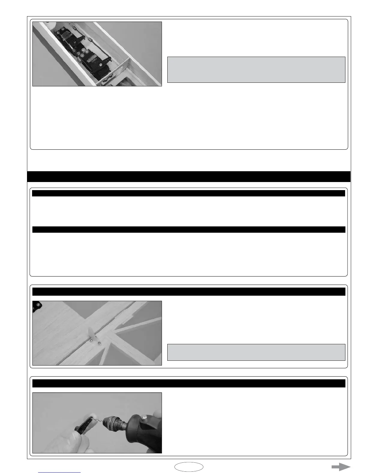
STEP 1: INSTALLING THE AILERON CONTROL HORNS
q Install one control horn onto the bottom of each aileron. Make sure that
the centerline of each control horn is 5-1/4" (133mm) out from the inside edge
of the ailerons (measured at the hinge line) and that the clevis attachment
holes are lined up over the hinge lines. The base of each control horn should
be perpendicular to the hinge line, too.
IMPORTANT Remember to apply a couple of drops of thin C/A into the
mounting holes to reinforce the surrounding wood.
STEP 2: INSTALLING THE AILERON CONTROL LINKAGE ASSEMBLIES
q Cut away all but one arm from a "4-point" servo horn.
q Enlarge the hole that is 3/4" (19mm) out from the center of the servo
horn, using a 5/64" (2mm) diameter drill bit.