Page 25
q Use a couple of pieces of masking tape, taped between the elevator and the stabilizer, to hold the elevator centered.
q Center the elevator servo, then attach the cable from the left side cable
guide to the Z-Bend coupler on the left side of the servo arm, then attach
the length of cable from the right side cable guide to the Z-Bend coupler on
the right side of the servo arm, using the same techniques that you used
to attach the threaded couplers.
IMPORTANT Make sure that both lengths of cable are pulled tight.
There should not be any slack in the cables.
q Remove the masking tape and double-check that both the servo horn and the elevator are still centered. If necessary, thread
the clevises in or out to center the elevator, then move the elevator up and down several times to ensure proper movement.
q Check the tension of the cables. To do this do the following: hold the elevator control stick all the way back. Let the control stick
go and check to see if the elevator returns to center. Do this a couple of times in each direction. If the elevator does not come back
to center, one or both cables are too tight. You can adjust the tension of the cables by adjusting the clevises. Ideally, the cables
should be as tight as possible, while still allowing the elevator to center. The cables should not have slack in them, yet they should
not be so tight that the linkage and/or the servo bind.
IMPORTANT Remember to apply a couple of drops of thin C/A to the crimp collets to make the joints even stronger.
RUDDER CONTROL SYSTEM INSTALLATION
YOU'LL NEED THE FOLLOWING PARTS FROM THE KIT:
YOU'LL NEED THE FOLLOWING TOOLS AND SUPPLIES:
q (1) Stranded Pull-Pull Cable
q (2) Control Horns
q (2) Clevises
q (2) Couplers with Z-Bends (Long)
q (2) Threaded Couplers
q (4) Flanged Crimp Collets
q (4) M2 x 16mm Machine Screws
q (4) M2 Hex Nuts
q Thin C/A
q # 1 Phillips Head Screwdriver
q Needle Nose Pliers
q Modeling Knife
q Electric Drill
q 1/16" (1.6mm) and 5/64" (2mm) Drill Bits
q Straight Edge Ruler
q Pencil
q Airplane Stand
q Masking Tape
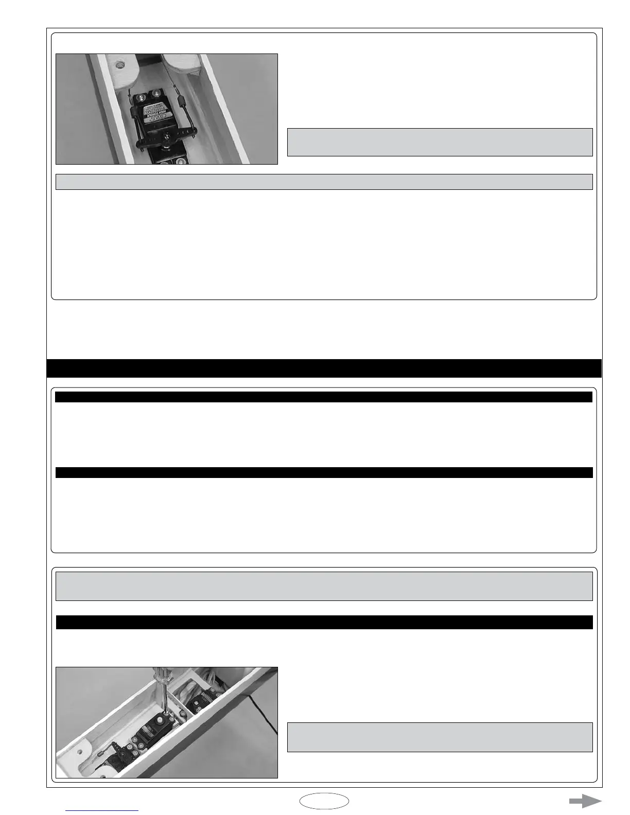
STEP 1: INSTALLING THE RUDDER SERVO
q Install the rudder servo onto the hardwood mounting blocks, making sure
to drill 1/16" (1.6mm) diameter pilot holes for the mounting screws.
IMPORTANT When installed, the servo output shaft must be toward
the front of the fuselage.
q Install the rubber grommets and brass collets onto your rudder servo, making sure to install the collets with the anges toward the
bottom of the servo.
IMPORTANT The rudder control system is installed using the same basic techniques that you used to install the elevator control
system. There are a couple of differences that are noted for you.