Page 32
ELECTRIC CONVERSION INSTRUCTIONS
YOU'LL NEED THE FOLLOWING PARTS FROM THE KIT:
YOU'LL NEED THE FOLLOWING TOOLS AND SUPPLIES:
q (4) M3 x 18mm Machine Screws
q (4) M3 Blind Nuts
q (4) M3 Flat Washers
q # 2 Phillips Head Screwdriver
q Wire Cutters
q Modeling Knife
q Scissors
q Electric Drill
q 1/8" (3mm), 1/4" (6mm) & 5/16" (8mm) Drill Bits
q Straight Edge Ruler
q Pencil
q Airplane Stand
q Masking Tape
q Soldering Iron
q Solder
q Heat Gun
IMPORTANT This section describes the installation of a brushless Outrunner power system that is mounted directly to the
rewall. This power system features the KMS Quantum 4120/05 Brushless Outrunner motor, Castle Creations Phoenix 60
Brushless ESC and the Impulse Power 4C 4000mAH LiPO battery. These instructions are general in nature, but should be similar
for most brushless Outrunner power systems. Your particular power system may come with mounting hardware, but if not, some
of the hardware included with the Magic 3D V2 ARF can likely be used. If not, you will need to purchase mounting hardware
separately for your particular application.
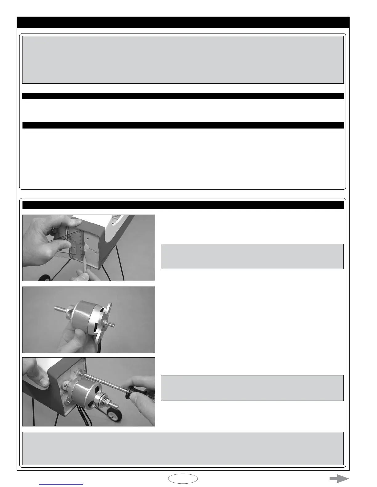
STEP 1: INSTALLING THE MOTOR
q Draw a horizontal centerline and a vertical centerline on the rewall to
help you line up your motor.
IMPORTANT The motor will be installed in the center of the rewall
and the back of the motor shaft will t in the middle of the precut fuel tank
stopper hole.
q Install your motor's motor mounting plate and propeller adapter using the
hardware provided with your motor.
IMPORTANT Using the power system that we suggest, the motor can be mounted ush to the rewall and still allow the airplane
to balance without needing to add nose weight. If your particular motor is lighter, or your power system differs from what's
suggested, it may be necessary for you to mount the motor further forward, so that the airplane will balance without needing to
add nose weight.
q Align your motor using the two centerlines that you drew. The center of
the motor should be lined up over the two centerlines.
IMPORTANT You may need to rotate the motor so that the precut
mounting slots in the rewall don't interfere with your motor mounting
holes.
q When satised with the alignment, mark and drill mounting holes through
the rewall, then install your motor using M3 x 16mm machine screws, M3
at washers and M3 blind nuts.