Page 13
YOU'LL NEED THE FOLLOWING PARTS FROM THE KIT:
YOU'LL NEED THE FOLLOWING TOOLS AND SUPPLIES:
q 5 and 30 Minute Epoxy
q Thin C/A
q C/A Debonder
q Modeling Knife
q Straight Edge Ruler
q Pencil
q T-Pins
q (1) Horizontal Stabilizer with Elevator and Hinges
q (1) Vertical Stabilizer with Rudder and Hinges
q (2) Triangle Supports
q Builder's Triangle
q 220 Grit Sandpaper with Sanding Block
q Masking Tape
q Paper Towels
q Rubbing Alcohol
q Epoxy Mixing Sticks
q Epoxy Mixing Cups
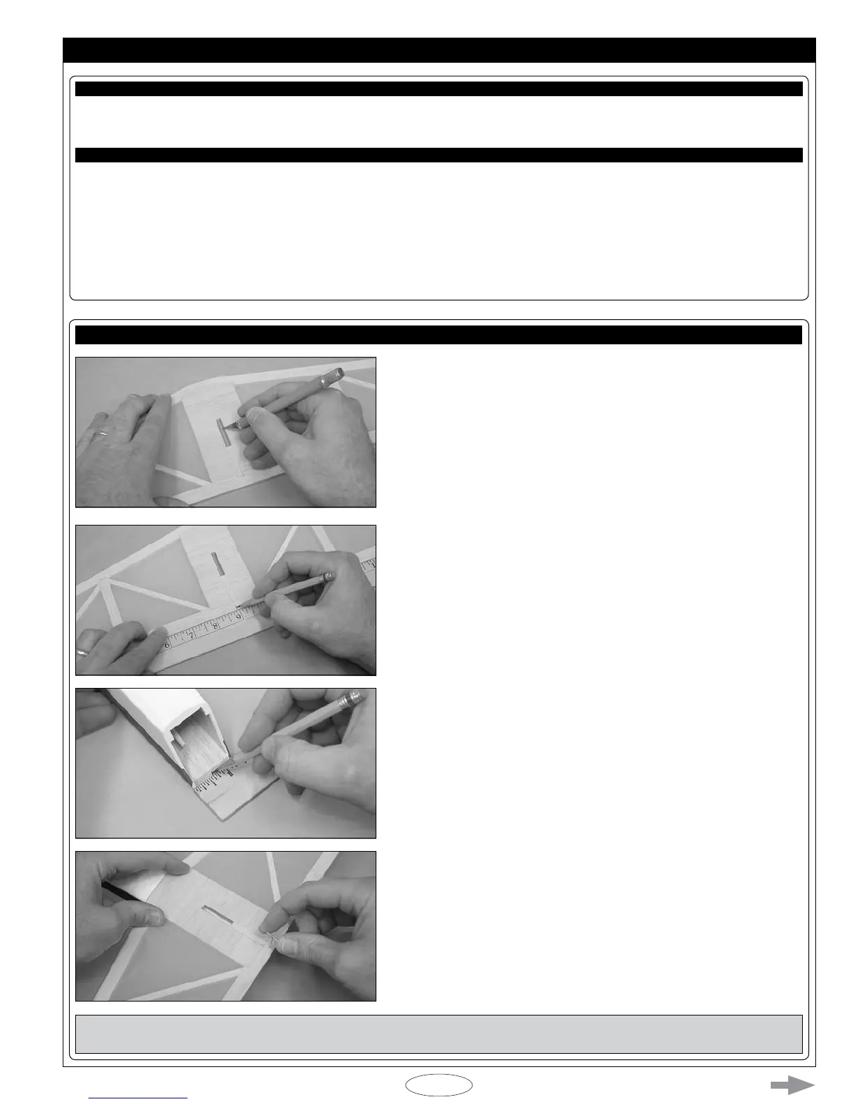
q Remove the elevator from the stabilizer and set it aside for now.
q Cut away the covering material from over the top and bottom of the slot
in the middle of the stabilizer.
q Measure and draw a centerline on the trailing edge of the stabilizer.
q Measure and draw a centerline on the bottom of the stabilizer mounting
platform on the fuselage.
q Set the stabilizer onto the stabilizer mounting platform, then line up the
centerline you drew on the stabilizer with the centerline you drew on the
fuselage.
q With the two centerline marks lined up and the trailing edge of the stabilizer
even with the back edge of the fuselage, hold only the trailing edge of the
stabilizer in position, using a T-Pin.
IMPORTANT The front of the stabilizer should be able to pivot from side to side and the back should stay rmly in place and
aligned. The trailing edge should not be allowed to move from side to side.