www.ModulusArms.com | AR-15 Jig Instructions
Figure 20: Fire Control Drill Depth
Milling the Fire Control Pocket
Configure Jig for Milling Fire Control Pocket: Remove the screws attaching the front and rear support to
the template. Remove the screws attaching the template to the side plates. Remove the template.
Remove the four screws attaching the drill guide to the template. Install the eight screws attaching the
supports and side plates to 1 ft-lb as shown in Figure 21.
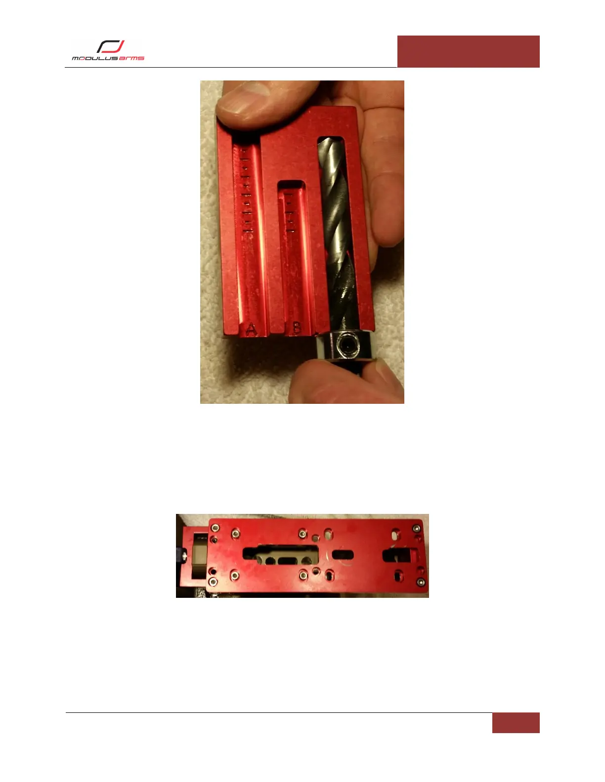
Figure 21: Fire Control Milling Configuration
Milling Fire Control Pocket: The end mill should already be installed in the router. Move the base of the
router until the tip of the end mill is at the first line in slot “C”, shown in Figure 22Figure 15. Place the
router into the fire control template and into the trigger slot opening you previously milled. You will
always use this as a starting location for this step. Be sure not to be touching the sides of the opening
when you start the router. Start the router and allow it to come completely up to speed. Start to move
the router removing material. Start by moving in semi-circular motion in small clockwise steps. Press