02/02 AWB8230-1447GB
1
Quick Reference Guide DF5 Frequency Inverter
Keypad
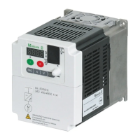
The following illustration shows the LCD keypad of the DF5.
Table 1: Explanation of the operating and indication elements
Figure 1: Keypad view
For an explanation of each of the elements, a table 1.
RUN
PRG
POWER
Hz
A
MIN
MAX
PRG
ENTER
a
k
j
i
hgf
e
d
c
b
Number Name Explanation
a RUN LED LED lights up in RUN mode if the
frequency inverter is ready for operation
or operational.
b
7 segment
display
Display for frequency, motor current,
fault messages, etc.
c
POWER LED LED is lit when the frequency inverter
has power.
d
Hz or A LED Indication in b: Output frequency (Hz)
or output current (A)
e
Potentiometer
and LED
Frequency setpoint setting
LED is lit when the potentiometer is
activated.
f
ENTER key This key is used for saving entered or
changed parameters.
g
Arrow keys
Selecting functions, changing numeric
values
Increase
Reduce
h
PRG key For selecting and exiting the
programming mode.
i
OFF key Stops the running motor and
acknowledges a fault message. Active
by default, also when actuation is
through terminals. This key is used for
saving entered or changed parameters.
j
On key
and LED
Starts the motor in the specified
direction (not active by default).
k
PRG LED LED is lit during parameterization. For
selecting and exiting the programming
mode.
ENTER
PRG

 Loading...