vi VERSAmax Tunable Microplate Reader Operator’s Manual
Figures
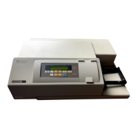
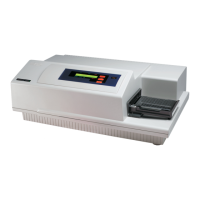
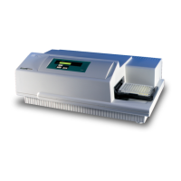
Figure 1.1: VERSAmax . . . . . . . . . . . . . . . . . . . . . . . . . . . . . . . . . . . . . . 1-3
Figure 1.2: Major Areas of the VERSAmax . . . . . . . . . . . . . . . . . . . . . . . .1-4
Figure 1.3: Control Panel . . . . . . . . . . . . . . . . . . . . . . . . . . . . . . . . . . . . . . .1-4
Figure 1.4: Microplate Drawer . . . . . . . . . . . . . . . . . . . . . . . . . . . . . . . . . .1-6
Figure 1.5: Components on the Back Panel of the
VERSAmax . . . . . . . . . . . . . . . . . . . . . . . . . . . . . . . . . . . . . . . . .1-7
Figure 2.1: View of Rear Panel . . . . . . . . . . . . . . . . . . . . . . . . . . . . . . . . . .2-4
Figure 4.1: Power Switch, Fuse Box, and Power Receptacle. . . . . . . . . .4-5
Figure 4.2: Removing the Fuse Box . . . . . . . . . . . . . . . . . . . . . . . . . . . . . .4-6
Figure 4.3: The Fuse Box and Holder (with Fuses) Removed. . . . . . . . .4-6
Table
Table 4.1: Error Codes. . . . . . . . . . . . . . . . . . . . . . . . . . . . . . . . . . . . . . 4-7



 To Next Page