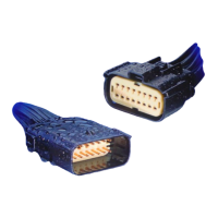
APPLICATION SPECIFICATION
REVISION: ECR/ECN INFORMATION: SHEET No.
EC No:
ABC2001-9999
1
DATE:
2008/16/03
TITLE:
MX150 Application Guide
35 of 62
DOCUMENT NUMBER: CREATED / REVISED BY: CHECKED BY: APPROVED BY:
Brian Zelinski Steve Verzyl Scott Marceau
TEMPLATE FILENAME: APPLICATION_SPEC[SIZE_A](V.1).DOC
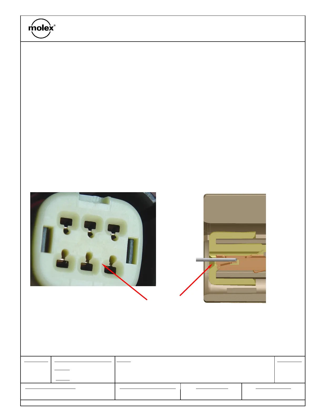
Section 6: Electrical Continuity Checking
B. Alternative method of probing
Fixtures used for continuity testing must meet the row and pitch dimensions
as identified in Section 6. Fixtures outside these requirements could result in
damage to the connector and/or terminal.
Molex Receptacle connector
female terminal
When TPA does not allow access to the box you must probe down the
throat using this method.
Shown below are pictures of MX150 Sealed connector. Unsealed
connectors must be probed at the same location (center of receptacle
TPA opening)
Check electrical continuity on the terminal by inserting probe pin down
the center of receptacle TPA opening
Must use this pin or damage will occur!
(0.64) mm probe