BM09201 Molift SMART 150 English - Rev C1/08/10 Page 5 of 20
Assembly / disassembly
Unpacking
• Theliftercomesinonecardboardbox.Verify
that the box has no apparent damage. If dam-
aged, check the content and contact your deal-
er for assistance if components are damaged.
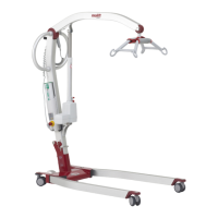
• TheboxcontainsonecompleteMoliftSmart
lifter with hand control, battery and battery
charger.
Assembly
The battery must not be in the battery holder
during assembly!
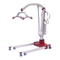
• Removethetransportelasticandspreadthe
legs to working position (maximum width).
The legs must be spread to working position
before the column can be mounted.
• Liftuptheliftingcolumnandslideitintothe
bracket on the chassis.
• Whenthecolumnhasplaceditselfinthebot-
tom of the bracket, it must be xed with the
locking handle on the back of the chassis. Push
the locking handle down (1) and make sure the
column is properly xed.
• Liftthesuspensionoutofthetransporthook.
Do not start to run the lifting arm before the
suspension is released!
• Insertthebatteryintothebatteryholderand
verify that the emergency stop button isn’t ac-
tivated.Runtheliftingarmupanddownwith-
out load to verify that it is working properly.
Check that the lifter is mounted correctly with
no loose part or damages. Ensure that the
lifting column is fixed properly, and that the
legs do not move inside working position.
Checklist after mounting.
• Checkthelifteraccordingtothechecklistbe-
fore use on page 7.
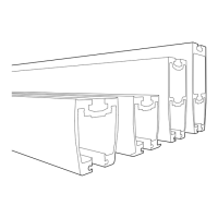
Transport position
Working position
The column must be
placed in the bottom of
the bracket on chassis as
shown on the illustration
to the left.
Max width