CUSTOMER SERVICE
If you have questions, comments or problems
visit our website revell.com or write to us at:
Revell Inc. Consumer Service
1850 Howard St. Unit A
Elk Grove Village, IL 60007
Be sure to include this plan number
(85006700200), part number, description and
your return address and phone number.
SERVICIO AL CLIENTE
Si tiene preguntas, comentarios o problemas,
visite nuestro sitio web revell.com
o escríbanos a:
Revell Inc. Consumer Service
1850 Howard St. Unit A
Elk Grove Village, IL 60007
Asegúrese de incluir el número de plano
(85006700200), el número de parte, la
descripción y su dirección y número de
teléfono para responder.
SERVICE À LA CLIENTÈLE
Pour toute question, problème ou commentaire,
visitez-nous à l’adresse revell.com ou
écrivez-nous à :
Revell Inc. Consumer Service
1850 Howard St. Unit A
Elk Grove Village, IL 60007
Assurez-vous d’inclure ce numéro de plan
(85006700200), le numéro de pièce, une
description ainsi que votre adresse de retour
et numéro de téléphone.
KIT 0067 85006700200
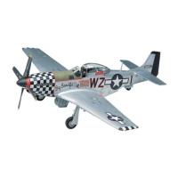
PHANTOM P-51D MUSTANG
It is considered, by historians and aircraft experts alike, to be the
best propeller driven fighter aircraft ever developed. The North
American P-51 Mustang changed the air war over Germany
during World War II. With the addition of disposable drop
tanks, the P-51 could escort the bombers all the way to the
target and back. The P-51 was such an effective fighter that it
was even used in the Korean War as a ground attack weapon.
The P-51 was originally developed in response to a purchase
order from the British during World War II. It was discovered in
the first flights, that more power was needed for it to be effective.
Switching to a British V-12 engine transformed the P-51 into
a magnificent fighter aircraft. It downed over 4,900 enemy
aircraft during World War II, in every different theater of the war.
Il est considéré par les historiens et les experts en aviation
comme le meilleur chasseur à hélice de tous les temps. Le
Mustang P-51 nord-américain a changé la guerre aérienne dans
le ciel d’Allemagne pendant la seconde guerre mondiale. En
plus de ses réservoirs de carburant largables, le P-51 pouvait
escorter les bombardiers jusqu’à leur cible puis en revenir. Le
P-51 était un chasseur tellement efficace qu’il a même été
utilisé dans la guerre de Corée comme arme d’attaque terrestre.
Le P-51 a été développé à l’origine en réponse à une commande
d’achat placée par les Britanniques pendant la seconde guerre
mondiale. On a découvert lors des premiers vols qu’il avait
besoin de plus de puissance pour être efficace. Un changement
pour des moteurs britanniques V-12 a transformé le P-51 en un
magnifique chasseur. Il a abattu plus de 4 900 ennemis pendant
la seconde guerre mondiale, sur tous les théâtres de bataille.
Los historiadores y los expertos en aviones consideran que es
el mejor avión de caza impulsado por hélice jamás desarrollado.
El Mustang P-51 de Norteamérica cambió la guerra aérea sobre
Alemania durante la Segunda Guerra Mundial. Con la adición
de tanques cisternas desechables, el P-51 podía acompañar
a los bombarderos en todo el camino hasta el objetivo y de
regreso. El P-51 fue un avión de caza tan eficaz que incluso se
utilizó en la Guerra de Corea como un arma de ataque en tierra.
El P-51 fue desarrollado originalmente en respuesta a
una orden de compra de los británicos durante la Segunda
Guerra Mundial. Se descubrió en los primeros vuelos, que se
necesitaba más potencia para que fuera eficaz. Al cambiar al
motor V-12 británico, se transformó el P-51 en un magnífico
avión de combate. Derribó 4.900 aviones enemigos durante la
Segunda Guerra Mundial, en los diferentes escenarios de la guerra.
READ THIS BEFORE YOU BEGIN
* Study the assembly drawings.
* Each plastic part is identified by a number.
* In the assembly drawings, some parts will
be marked by a star
★
to indicate chrome
plated plastic.
* For better paint and decal adhesion,
wash the plastic parts in a mild detergent
solution. Rinse and let air dry.
* Check the fit of each piece before
cementing in place.
* Use only cement for polystyrene plastic.
* Scrape plating and paint from areas to
be cemented.
* Allow paint to dry thoroughly before
handling parts.
* Any unused parts may be discarded.
LISEZ CECI AVANT DE COMMENCER
* Étudiez les plans d’assemblage.
* Chaque pièce de plastique est identifiée
par un numéro.
* Dans les plans d’assemblage, certaines
pièces seront marquées d’une étoile
★
pour indiquer des pièces en plastique
plaquées chrome.
* Pour une meilleure adhésion de la peinture
et de la décalcomanie, lavez les pièces en
plastique dans une solution de détergent
doux. Rincez et laissez sécher à l’air.
* Vérifiez l’ajustement de chaque pièce avant
de la coller en place.
* Utilisez uniquement de la colle pour
plastique au polystyrène.
* Grattez toute peinture et le placage sur les
régions à coller.
* Laissez sécher la peinture complètement
avant de manipuler des pièces.
* Toute pièce non-utilisée peut être jetée.
LEA ESTO ANTES DE EMPEZAR
* Estudie los dibujos de ensamblaje.
* Cada parte plástica está identificada con
un número.
* En los dibujos de ensamblaje, algunas
partes aparecerán marcadas con una
estrella
★
para indicar plástico enchapado
en cromo.
* Para mejor adhesión de pintura y
calcomanías, lave las partes plásticas
en una solución de detergente suave.
Enjuague y deje secar al aire.
* Verifique el encastre de cada pieza antes
de cementar en su lugar.
* Use sólo cemento para plástico de
poliestireno.
* Raspe las placas y la pintura de las áreas
a cementar.
* Deje secar la pintura totalmente antes
de manipular las partes.
* Cualesquiera partes sin usar se
pueden descartar.
Kit 0067 - Page 32
Revell Inc Elk Grove Village, IL. Copyright © 2014. All rights reserved.
39