112
MONTEREY
BOATS
Ventilation System
A carbon monoxide detector has been installed
in the cabin as standard equipment. While a
CO detector enhances your protection from CO
poisoning, it does not guarantee it will not occur.
Do not use the carbon monoxide detector as a
replacement for ordinary precautions or periodic
inspections of equipment. Never rely on alarm
systems to save your life, common sense is still
prudent and necessary. Remember, the operator
of the boat carries the ultimate responsibility to
make sure the boat is properly ventilated and the
passengers are not exposed to dangerous levels
of carbon monoxide. You should always be alert
to the symptoms and early warning signs of car-
bon monoxide poisoning. You also should read
the “Carbon Monoxide Monitoring System” in the
Safety Equipment chapter of this manual, and
the owner’s manual supplied by the CO detector
manufacturer for operation instructions and ad-
ditional information regarding the hazards and
symptoms of carbon monoxide poisoning.
ACTIVATION OF THE CARBON MONOXIDE DETECTOR
INDICATES THE PRESENCE OF CARBON MONOXIDE (CO)
WHICH CAN BE FATAL. EVACUATE THE CABIN IMMEDIATELY.
DO A HEAD COUNT TO CHECK THAT ALL PERSONS ARE
ACCOUNTED FOR. DO NOT REENTER THE CABIN UNTIL
IT HAS BEEN AIRED OUT AND THE PROBLEM FOUND AND
CORRECTED.
PERIODICALLY TEST THE CARBON MONOXIDE ALARMS PER
THE MANUFACTURER’S INSTRUCTIONS. PLEASE REFER TO
THE CARBON MONOXIDE ALARM MANUAL OR CONTACT THE
MANUFACTURER FOR MORE INFORMATION ON MAINTAINING
AND CALIBRATING THE ALARM.
10.3 Engine Compartment Ventilation
All Monterey inboard boats are equipped with an
engine compartment ventilation system consisting
of intake ducts, exhaust ducts and exhaust blow-
ers. The ventilation system is designed to meet
or exceed the requirements of the United States
Coast Guard in effect at the time of manufacture
and remove fuel vapors and excess heat from the
engine room.
Free Air System
-
vided by two vents located on either side of the
deck. Exhaust ventilation designed into the vents
-
ment. The exhaust area of the vents have ducts
that reach to the lower part of the engine com-
partment. This provides adequate air movement
while operating at or near cruise speeds.
prevent seawater or spray from entering the
engine or storage compartments while providing
adequate air movement for the engine. On some
transom storage compartments and then to the
engine compartment. Therefore, it is important
the point the stowed items severely restrict the
Forced Ventilation
Electric blowers provide ventilation to the engine
compartment prior to start up of the main engines
or optional generator and while operating below
cruise speed or running the generator. The blow-
ers are activated by a switch at the helm or in the
generator control panel. The blowers are located
in the engine compartment exhaust vent hoses.
When activated, the blowers will remove bilge
fumes through the exhaust vents. Refer to the
Electrical Systems chapter for more information
on blower operation.
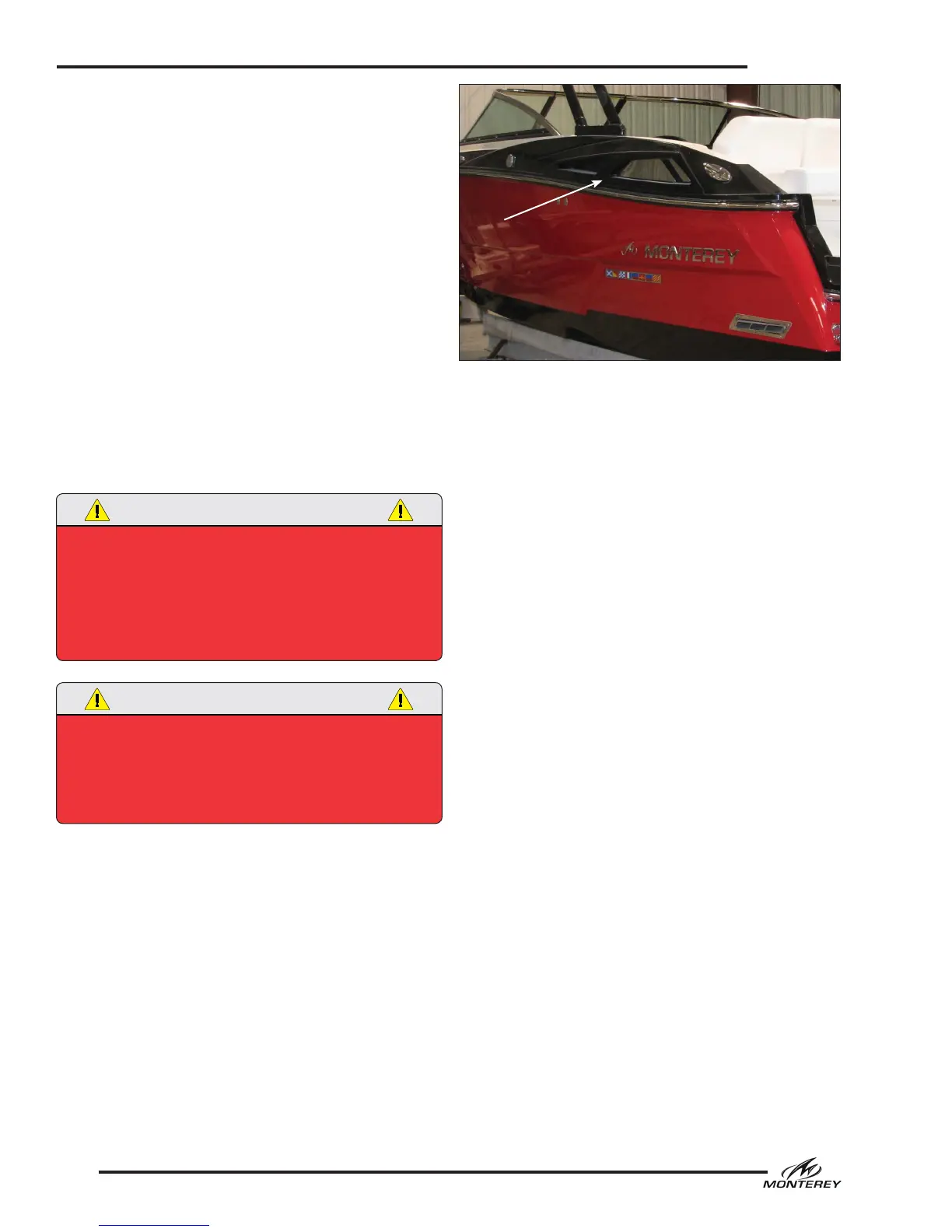
Typical Engine Compartment Vents



 To Next Page