87
MONTEREY
BOATS
Electrical System
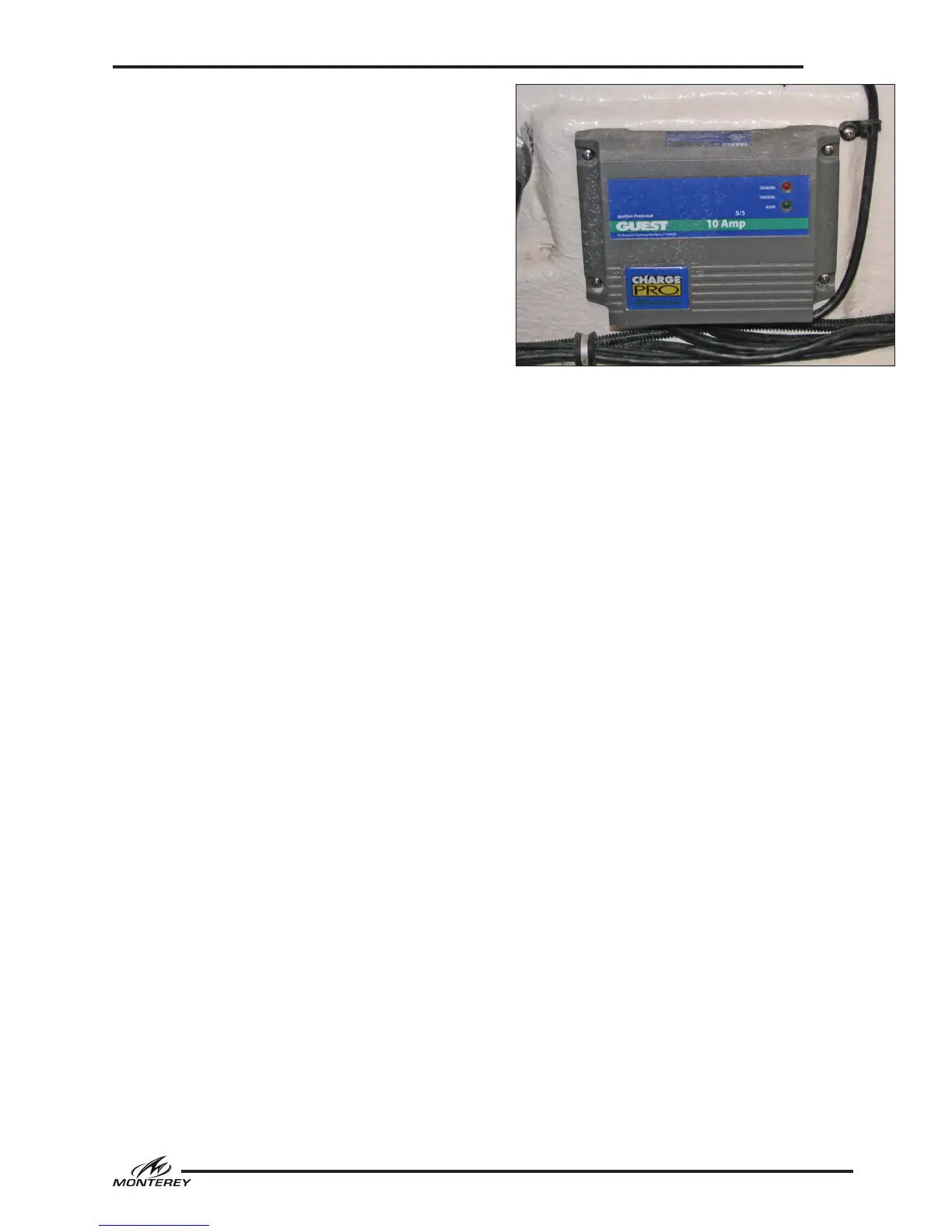
6.8 Battery Charger
A battery charger mounted in the engine compart-
ment is optional equipment on some models. AC
electrical current is supplied either directly to the
automatic battery charger or by a circuit breaker
in the cabin AC breaker panel. The battery char-
ger automatically charges and maintains the 12
volt batteries simultaneously when activated. It
is fully automatic and equipped with led lights to
indicate the state of charge for each battery and/
or a voltmeter in the cabin DC breaker panel on
328SS models.
Charging for the batteries also can be monitored
by using the voltmeter in the engine gauge cluster.
With the charger activated, turn the ignition key
switch for each engine to the “ON” position. DO
NOT START THE ENGINE. Then read the voltage
on the volt meter. If the batteries are in good
condition and charging properly, the voltmeter
will indicate between 12 and 14.5 volts. If the
reading is below 12 volts, then the battery is not
accepting a charge or the charger is not working
properly. Always turn the ignition switches off
immediately after the monitoring is complete.
The wires that supply DC charging current to the
batteries are protected by an internal fuse in the
battery charger and external fuses, one for each
battery output wire, located near each battery.
The external fuses protect the DC charging circuit
from the batteries to the charger. The internal
fuses in the charger protect the DC charging circuit
from the charger to the batteries. See the battery
charger manual for more information.
6.9 DC To AC Power Inverter (328SS)
Power Inverter General
A 12 volt DC to 120 volt AC power inverter is
available as optional equipment on some models.
A remote switch panel controls the inverter that
converts 12 DC electrical power from the batteries
to 120 volt AC power for the optional cockpit grill.
Inverters draw a substantial amount of current
from the house batteries. It takes approximately
20 amps 12-volt DC current to provide 2 amps 120
volt AC current. Therefore, you should only use
the Bat’ save mode when shore or generator AC
power is not available to maintain the house bat-
teries with the battery charger while the inverter
is activated.
The ON/OFF switch turns the Inverter to ON or
OFF. In the ON position, the Inverter/Fault LED
Typical Battery Charger
light will illuminate green. The inverter begins
In this position the inverter will continue to supply
AC power until the house batteries are depleted.
The battery charger should be activated and main-
taining the house battery whenever the inverter
switch is in the ON position. In the OFF position
the inverter draws no current from the battery.
Bat’ Saver mode is the preferred setting, par-
ticularly when shore or generator AC power is
not available to maintain the house Batteries.
Bat’ Saver mode allows the user to protect from
draining down the entire power of the house
battery and shuts the inverter off when the bat-
tery reaches a threshold of 11.7 volts, allowing
the other DC accessories to continue to operate
normally and preventing excessive drain on the
battery. To use the Bat’ Saver mode, turn the ON/
OFF switch to the Bat’ Saver mode.
Two indicator lights on the panel illustrate the op-
erating status of the Inverter. When the inverter
is on and supplying power normally the green light
glows. The red “fault light” glows when there is
a battery over voltage, low battery voltage, out-
put overload or an over temperature condition
in the inverter. Refer to the inverter operating
manual for more information on the operation of
the inverter.
 Loading...