89
MONTEREY
BOATS
Electrical System
Recommended procedure for making a
shore connection:
Turn the AC Shore Main breakers to the “OFF” posi-
tion. If the dockside outlet includes a disconnect
switch, turn it to the “OFF” position also.
To avoid strain on the cable make sure it has more
slack than the mooring lines. Dress the cable so it
and the dock. Make sure the cable doesn’t come
in contact with the water and connect the cable
to the boat inlet plug and then to the dockside
outlet, making sure the connection plugs include
a three-prong plug with a ground wire. Tighten
the lock rings on both the shore and the boat
connector plugs.
Turn the dockside disconnect switch or circuit
breaker to the ON position. Then turn the circuit
breaker at the boat inlet plug on and check for
proper polarity. If reversed polarity has been
achieved, the red reversed polarity indicator in the
cabin AC panel will light. If this should happen,
make sure the Shore Main breaker on the panel
is in the “OFF” position and turn the dock power
switch or breaker off. If the Shore Main light il-
luminates and the red Reversed Polarity light does
not illuminate when power is supplied to the panel
the polarity is correct and the AC main breaker
can be moved to the “ON” position.
Check the ELCI panel in the engine compartment
for faults. The green “POWER” LED should show
steady illumination and the red “FAULT” LED
should remain off. The ELCI trips and opens the
main circuit when there is a ground fault condi-
tion. If the red LED is continuously illuminated
the ELCI has tripped due to a ground fault condi-
tion. Some faults are self-clearing. Try resetting
the ELCI once. If the green LED shows steady
illumination and the ElCI does not trip again, the
circuit is correct and activated.
If the reversed polarity light is lit or the ELCI con-
tinues to trip and the red “FAULT” LED is lit after
being reset there is a problem with the AC electri-
cal system and it is unsafe to use. Make sure the
Shore Main breaker on the panel is in the “OFF”
position and turn the dock power switch or breaker
off. Disconnect the shore power supply cord from
to check the wiring and correct the problem.
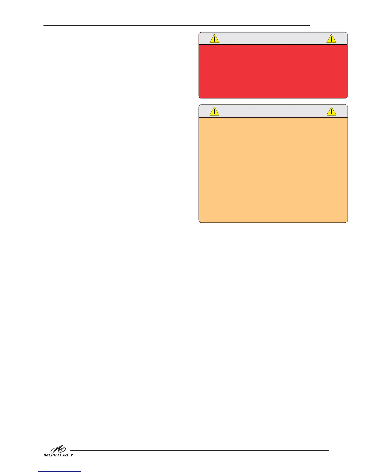
REVERSED POLARITY AND GROUND FAULT CONDITIONS
WILL DAMAGE THE SYSTEM AND EXPOSE PASSENGERS
TO ELECTROCUTION HAZARDS THAT WILL CAUSE SEVERE
INJURY OR DEATH. THIS CONDITION COULD ALSO CAUSE
A FIRE IN THE ELECTRICAL SYSTEM. NEVER OPERATE THE
AC ELECTRICAL SYSTEM WITH REVERSED POLARITY OR A
GROUND FAULT CONDITION.
ELECTRIC SHOCK CAN CAUSE SEVERE INJURY OR EVEN
DEATH. DO NOT ATTEMPT TO CORRECT THE WIRING
YOURSELF. ALWAYS HAVE A QUALIFIED ELECTRICIAN CHECK
WIRING.
KEEP CHILDREN AWAY FROM ANY ELECTRICAL CABLES OR
EQUIPMENT AND ALWAYS USE GROUNDED APPLIANCES ON
BOARD YOUR BOAT.
UNDETECTED FAULTS IN THE AC ELECTRICAL SYSTEM
COULD CAUSE THE WATER AROUND THE BOAT TO BECOME
ENERGIZED. THIS COULD CAUSE A SEVERE SHOCK OR
EVEN DEATH TO SOMEONE IN THE WATER NEAR THE BOAT.
NEVER SWIM OR ALLOW SWIMMING AROUND THE BOAT
WHEN THE AC SYSTEM IS ACTIVATED BY THE SHORE POWER
CONNECTION OR THE GENERATOR.
Disconnecting procedure for shore power
connection:
Turn the Shore Main breaker on the AC panel to
the “OFF” position. Turn the disconnect breaker
on the dockside outlet to the “OFF” position.
Disconnect the cable from the dockside outlet and
replace the outlet caps. Disconnect the cable from
the boat and replace the outlet cap. Store cable.
Equipment Leakage Circuit Interrupter
The ELCI provides whole-boat ground fault pro-
tection (electrical shock protection from stray
current) for the entire AC shore power system.
The ELCI face plate in the engine compartment is
equipped with TEST and RESET buttons. There
are also two LED lights that indicate circuit status.
When the 120 volt AC system is activated, the
green “POWER” LED should show steady illumina-
tion and the red “FAULT” LED should remain off.
The ELCI trips and opens the main circuit when
there is a ground fault condition. If the red
“FAULT” LED is continuously illuminated the ELCI
has tripped due to a ground fault condition. Some
faults are self correcting. If it trips, try resetting
the ELCI once. If the green LED shows steady
illumination and the ELCI does not trip again, the



 To Next Page