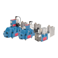
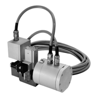
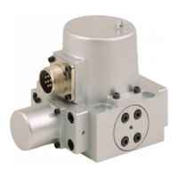
The Moog D680 Series Proportional Control Valves are 2-stage, pilot-operated valves with integrated electronics, designed for demanding applications requiring high precision and dynamics. These valves are available in various sizes (D681, D682, D683, D684, D685) and offer a range of features to suit diverse industrial needs.
Function Description:
The D680 Series valves are 2-stage proportional control valves that combine a dynamic pilot stage, a flow-optimized main stage, and integrated electronics. The pilot valve, a 4/3-way servo valve, is driven by a linear force motor. This motor consists of a coil, permanent magnets, pole pieces, an armature, and a centering spring. The armature is linked to a spool that moves within a bushing inside the pilot valve housing, controlling the flow from the pilot pressure port to the main stage spool's control chambers.
When a PWM current is applied to the coil, an electromagnetic field is generated, displacing the armature and the pilot valve's spool. The direction of displacement depends on the current's polarity. The centering spring provides an opposing force, making the spool's displacement proportional to the applied PWM current. In the center position, defined by the centering spring, the linear force motor consumes no current, leading to low energy consumption during standby or constant spool positions.
The valves can be configured for fail-safe operation. Biased pilot valves mean the spring-centered position is outside the true center, causing the main stage spool to move to a defined end position if the electronic supply fails or is switched off, provided pilot supply is active. This is crucial for fail-safe functions where the main stage spool needs to be in a non-centered position during failure. For applications requiring a centered spool in case of failure, an unbiased pilot valve combined with a 4/2-way solenoid valve is used. The 4/2-way solenoid valve can override the pilot valve, uncoupling it from the main stage and allowing springs to move the main spool to a defined position (center, slightly opened, or fully opened).
Important Technical Specifications:
- Valve Design: 2-stage, with standard or stub shaft spool.
- Pilot Valve: D633 unbiased or D633 biased options.
- Mounting Pattern: ISO 4401-05-05-0-05 (D681), ISO 4401-07-07-0-05 (D682), ISO 4401-08-08-0-05 (D683, D684), ISO 4401-10-09-0-05 (D685).
- Operating Pressure (Main Stage): Up to 350 bar (5,000 psi) for ports P, A, B, and T at Y external.
- Operating Pressure (Pilot Valve): Minimum 10 bar (145 psi) above T or Y, range 10 to 350 bar (145 to 5,000 psi) for X port, maximum 70 bar (1,000 psi) for Y port.
- Rated Flow (at Δp_N 5 bar):
- D681: 30/60/80/2 x 80 l/min (7.9/15.9/21.1/2 x 21.1 gpm)
- D682: 150/250 l/min (39.6/66.0 gpm)
- D683: 350 l/min (92.4 gpm)
- D684: 550 l/min (145.3 gpm)
- D685: 1,000 l/min (264.2 gpm)
- Maximum Flow:
- D681: 180 l/min (47.6 gpm)
- D682: 600 l/min (158.5 gpm)
- D683: 1,100 l/min (290.6 gpm)
- D684: 1,500 l/min (396.3 gpm)
- D685: 3,600 l/min (951 gpm)
- Step Response Time (0 to 100% stroke):
- D681: 11 ms (unbiased), 13 ms (biased)
- D682: 11 ms (unbiased), 13 ms (biased)
- D683: 13 ms (unbiased), 18 ms (biased) for standard spool; 10 ms (unbiased), 13 ms (biased) for stub shaft spool.
- D684: 18 ms (unbiased), 26 ms (biased) for standard spool; 12 ms (unbiased), 16 ms (biased) for stub shaft spool.
- D685: 35 ms (unbiased), 40 ms (biased).
- Electrical Data:
- Supply Voltage: 24 VDC (18 to 32 VDC).
- Degree of Protection: IP65 (with mounted mating plugs).
- Maximum Current Consumption: 0.3 A (static), 1.2 A (dynamic).
- Fuse Protection: 1.6 A (slow) for D681-D684, 2 A (slow) for D685.
- Hydraulic Fluid: Hydraulic oil as per DIN 51524 parts 1 to 3 and ISO 11158.
- Recommended Cleanliness Class (ISO 4406): 18/15/12 for functional safety, 17/14/11 for longer service life.
Usage Features:
- Cost-effective and High-performance: Provides reliable control in demanding applications.
- Optimized Flow: Valve housing ensures maximum flow for the given nominal size, enhancing energy efficiency and system sizing.
- Improved Dynamic Response: Achieves performance comparable to 3-stage valves, especially with stub-shaft spool versions (D683, D684) that require reduced flow to move the spool.
- Integrated Fail-Safe Options: Minimizes the need for additional components, enhances user safety, lowers costs, and reduces machine complexity.
- Full System Pressure Handling: Pilot stage can handle full system pressure of 350 bar (5,000 psi), eliminating the need for additional components to reduce pilot pressure.
- Tuneable System: Dual gain and curvilinear spool options, along with a user-accessible electrical null adjust potentiometer, allow for better resolution in various machine applications.
- Robust Design: Special versions with hardened valve housing reduce wear, decoupled electronics withstand high shock and vibration, and compatibility with special fluids make them ideal for demanding environments, increasing uptime and extending valve life.
- Low Pilot Stage Leakage: Direct drive pilot valves reduce system losses, improve efficiency, and save energy, particularly in multi-valve systems.
- High Dynamics: Nearly independent of operating pressure, providing excellent dynamics for high-performance applications requiring higher acceleration and accuracy.
- 5-Port Version (D681-D684): Available for regenerative circuits, allowing flow from the rod side of the differential cylinder to be directly fed into the bore side, creating a permanent regenerative circuit when extending the cylinder.
- High-Flow Version (D684): For 3/3-way applications, offering higher rated flow by combining two ports for flow in one direction.
Maintenance Features:
- Service Sealing Sets: Available for both main stage and pilot valve/4/2-way solenoid valve, including O-rings and Kantseals made of FKM, NBR, or HNBR for different sizes.
- Flushing Plates: Available for various port configurations (P-A-B-T-T₁-X-Y, P-T-T₁-X-Y, P-T-T-X-Y, P-T or P-T-X or P-T-X-Y adjustable, P-A-B-T-X-Y, P-B and A-T-X) with mounting screws and O-rings included.
- Manifolds: ISO 4401 compliant manifolds for different sizes, with specified port connections.
- Mounting Screws: Available in various sizes (M6x40, M6x55, M10x60, M12x75, M20x90) with specified tightening torques.
- Shipping Plates: ISO 4401 compliant for different sizes.
- Mating Connectors: Straight and elbow 6-pole + PE connectors, and straight 11-pole + PE connectors, in accordance with EN 175201-804, metal, IP65, with various cable diameters and sealing elements.
- Power Supply Cable: 2 m (6.4 ft) length.
- SELV Power Pack: 24 VDC, 10 A.
- Technical Notes: Comprehensive documentation available for protective grounding, electrical shielding, wiring instructions, and maximum permissible length of electric cables.
- Global Support: Moog offers factory repair services, replacement parts/spares, professional field services, and flexible service agreements to maximize uptime and protect investment.