42Rev. C, April 2017
TECHNICAL DATA Moog D680 Series Proportional Control Valves
ELECTRONICS
42
TECHNICAL DATA
Rev. C, April 2017
Moog D680 Series Proportional Control Valves
ELECTRONICS
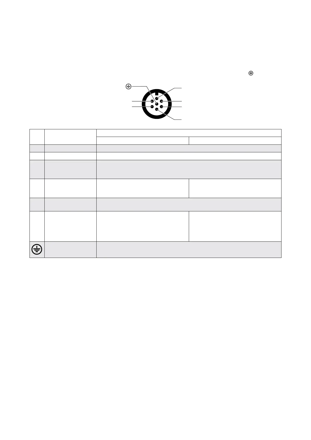
Pin Assignment for Valves with 6-pole + PE Connector, Pin Contacts
According to EN 175201-804, mating connector (type R or S, metal) with preleading protective earth pin ( )
B
C
D
F
E
A
Pin Pin assignment Signal type
1)
Voltage floating Current floating
A Supply voltage U
A-B
= 24 V
DC
(18 to 32 V
DC
) referenced to GND (reverse polarity protected against GND)
B GND Power ground/signal ground
C Enable input U
C-B
> 8.5 to 32 V
DC
referenced to GND: Valve ready for operation (enabled)
U
C-B
< 6.5 V
DC
referenced to GND: Valve disabled
The input resistance is 10 kΩ
D Command signal -
spool position
U
in
= U
D-E
R
in
= 10 kΩ
I
in
= I
D
= -I
E
R
in
= 200 Ω
I
max
= ±25 mA
E Reference point
Input rated command
Reference for pin D
2)
F Actual value -
spool position
U
F-B
= 2 to 10 V; U
F-B
is proportional to the
spool position; 6 V corresponds to the
spool center position; R
L
= 500 Ω
4 to 20 mA referenced to GND; I
out
is
proportional to the spool position; 12 mA
corresponds to the spool center position;
the output is short-circuit-proof; R
L
= 100
to 500 Ω
Protective earth (PE) Connected with valve body
1) Signal ranges see next page.
2) The potential difference between pins D or E referenced to pin B must be between -15 and +32 V.