43Rev. C, April 2017
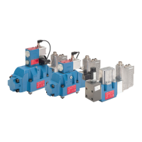
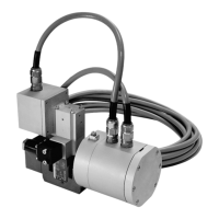
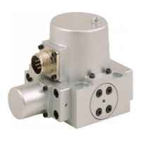
TECHNICAL DATA Moog D680 Series Proportional Control Valves
ELECTRONICS
43
TECHNICAL DATA
Rev. C, April 2017
Moog D680 Series Proportional Control Valves
ELECTRONICS
Ordering Codes and Signals for Valves with 6-pole + PE Connector
Ordering code
position 10
Command signal ±100% spool position Actual value ±100 % spool position
D U
D
- U
E
-10 to +10 V U
F
- U
B
2 to 10 V
M U
D
- U
E
-10 to +10 V I
F
4 to 20 mA
X I
D
-10 to +10 mA I
F
4 to 20 mA
E I
D
4 to 20 mA I
F
4 to 20 mA
Note: For more information see Technical Notes TN 353 “Protective Grounding and Electrical Shielding of Valves“, TN 426 “Wiring
Instructions“ and TN 494 “Maximum Permissible Length of Electric Cables for Valves with Integrated Electronics“.
Visit www.moog.com to download document.
Note: See inside back cover for complete ordering information.
Command Signal Current Floating,
Ordering Code X or E
The spool position is proportional to I
D
= -
I
E
.
For a command signal I
D
= 20 mA the spool moves to 100 %
P → A and B → T.
For a command signal I
D
= 12 mA the spool is in the defined
center position.
Command Signal Voltage Floating,
Ordering Code D or M
The spool position is proportional to U
D
−
U
E
.
For a command signal U
D
−
U
E
= +10 V the spool moves to
100 % P → A and B → T.
For a command signal U
D
−
U
E
= 0 V the spool is in the
defined center position.
Actual Value 4 to 20 mA, Ordering Code M, X or E
The signal can be used for monitoring and fault detection
purposes. The spool position is proportional to I
out
. The
spool position corresponds to 4 to 20 mA. At 12 mA the
spool is in center position.
20 mA corresponds to 100 % valve opening P → A and
B → T. A cable fault is detected by I
out
= 0 mA.
Actual value U
out
= 2 to 10 V with resistor R
L
= 500 Ω
(0.25 W) provided by customer.
I
out
R
L
V
U
out
I
out
F
B
(GND)
Valve Spool
position
R
in
0 V +24 V
D
E
B
A
I
E
U
DE
Valve
Control
I
Command signal
Command signal I
D
GND
R
in
0 V +24 V
D
E
B
A
U
DE
Supply
Control
U
Command signal
Signal
Valve
Command signal
Actual Value 2 to 10 V, Ordering Code D
The signal can be used for monitoring and fault detection
purposes. The spool position is proportional to U
out
. The
spool position corresponds to 2 to 10 V. At 6 V the spool is
in center position.
10 V corresponds to 100 % valve opening P → A and B → T.
A cable fault is detected by U
out
= 0 V.
R
L
= 500 Ω (0.25 W).
I
out
R
L
V
U
out
I
out
F
B
(GND)
Valve Spool
position