44Rev. C, April 2017
TECHNICAL DATA Moog D680 Series Proportional Control Valves
ELECTRONICS
44
TECHNICAL DATA
Rev. C, April 2017
Moog D680 Series Proportional Control Valves
ELECTRONICS
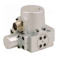
Pin Assignment for Valves with 11-pole + PE Connector, Pin Contacts
According to EN 175201-804, mating connector (type E, metal) with preleading protective earth pin ( )
54
3
2
9 11
8
7
6
1
Pin Pin assignment Signal type
1)
Voltage floating Current floating
1 Supply voltage U
1-2
= 24 V
DC
(18 to 32 V
DC
) referenced to GND (reverse polarity protected against GND)
2 GND Power ground/signal ground (enable and output)
3 Enable input U
3-2
> 8.5 to 32 V
DC
referenced to GND: Valve ready for operation (enabled)
U
3-2
< 6.5 V
DC
referenced to GND: Valve disabled
The input resistance is 10 kΩ
4 Command signal -
spool position
U
in
= U
4-5
R
in
= 10 kΩ
I
in
= I
4
= -I
5
R
in
= 200 Ω
I
max
= ±25 mA
5 Reference point
Input rated command
Reference for pin 4
2)
6 Actual value -
spool position
U
6-2
= 2 to 10 V. At 6 V spool is in centered
position. R
L
= 500 Ω
4 to 20 mA referenced to GND (I
out
is
proportional to the spool position, 12 mA
corresponds to the valve middle position,
the output is short-circuit-proof); R
L
= 100
to 500 Ω
7 U
7-2
: 13 to 3 V referenced to GND (U
7-2
is proportional to the spool position, 8 V
corresponds to the valve middle position, the output is short-circuit-proof); R
L
= 5 kΩ
8 Digital output - valve
status
U
8-2
> 8.5 V: Valve ready for operation
(enabled and supply OK).
U
8-2
< 6.5 V: Valve disabled.
Load type: Ohmic, inductive, lamp load.
I
max
= 20 mA (short-circuit-proof).
U
8-2
> 8.5 V: Valve ready for operation
(enabled and supply OK).
U
8-2
< 6.5 V: Valve disabled.
Load type: Ohmic, inductive, lamp load.
Output current maximum 1.5 A (short-
circuit-proof).
9 Optional - fail-safe
valve supply
U
9-10
= 24 V
DC
(22.8 to 26.4 V
DC
) referenced to failsafe valve GND (reverse polarity
protected against GND); I
max
= 1.35 A, 36 W
10 Optional - fail-safe
valve GND
Power ground - fail-safe valve
11 Digital output - error
monitoring
U
11-2
> 8.5 V: No error.
U
11-2
< 6.5 V: Indicates error
3)
.
Load type: Ohmic, inductive, lamp load.
I
max
= 20 mA (short-circuit-proof)
4)
.
Protective earth (PE) Connected with valve body
1) Signal ranges see next page.
2) The potential difference between pins 4 or 5 referenced to pin 2 must be between -15 and +32 V.
3) Output can be programmed at the factory, enable function order code: K and L - safe position of spool, M and R - command signal/
actual valve deviation, others upon request.
4) The currents drawn at the outputs pin 11 (referenced to GND) must be added to the valve supply current. The valve fuse must be
configured for the total current.