41Rev. C, April 2017
TECHNICAL DATA Moog D680 Series Proportional Control Valves
SIZE 10 - D685 PROPORTIONAL VALVE
41
TECHNICAL DATA
Rev. C, April 2017
Moog D680 Series Proportional Control Valves
SIZE 10 - D685 PROPORTIONAL VALVE
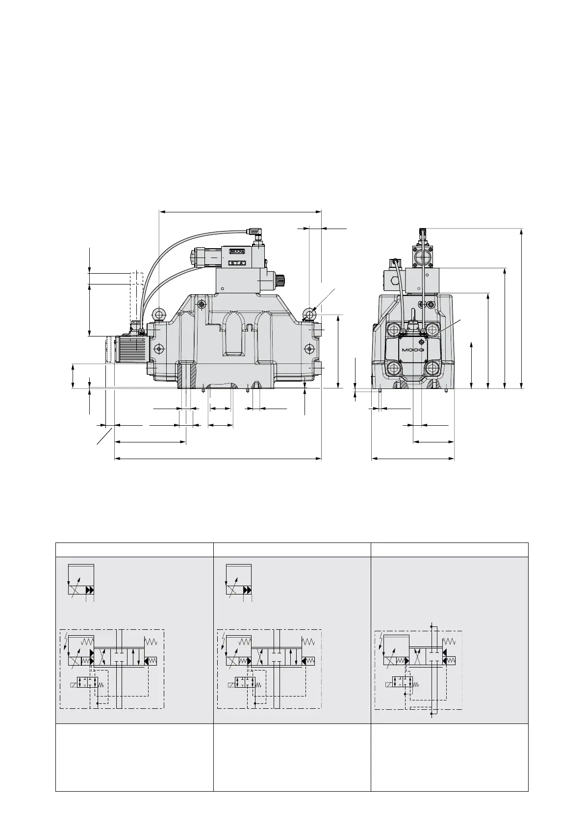
Installation Drawing for Fail-safe Options U and W
Y X
1
11+PE
(6+PE)
2
(2.32)
2.7
(0.11)
1.3
(0.05)
177
(6.96)
8
(0.32)
16
(0.63)
ø
390
(15.35)
29
(1.14)
111.8
(4.40)
229
(9.02)
289
(11.38)
384
(15.12)
17.2
(0.68)
ø
22
(0.87)
ø
ø
50
(1.97)
ø
33
(0.79)
ø
60
(2,36)
172
(6.77)
497
(19.56)
6
(0.24)
ø
20
(0.79)
99
(3.90)
199
(7.84)
20
(0.79)
125
(4.92)
Mating connector
Headrom for
disconnecting
[85]
[(3.35)]
21
(0.83)
Installation drawing
1 Electric null adjust (behind screw plug)
Attention! Electric null adjust is not possible if the position of the main spool is monitored!
2 With dampening plate
Optional X and Y external Optional X and Y external X and Y external necessary
TP
YX
BA
TP
YX
BA
YX TP
Fail-safe option U
4-way design
Fail-safe position P → B and defined
center position
Fail-safe option W
4-way design
Defined center position
Fail-safe option W
2x2-way design
Defined center position by mechanical
spool stop
Flow direction only according to
symbol