11Rev. C, April 2017
TECHNICAL DATA Moog D680 Series Proportional Control Valves
SIZE 05 - D681 PROPORTIONAL VALVE
11
TECHNICAL DATA
Rev. C, April 2017
Moog D680 Series Proportional Control Valves
SIZE 05 - D681 PROPORTIONAL VALVE
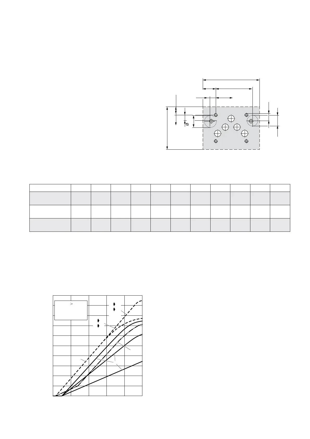
Hole Pattern of Mounting Surface
The mounting manifold must comform to
ISO 4401-05-05-0-05.
Clamping length minimum 100 mm (3.94 in)
• For valves of 4-way design with Q
N
> 60 l/min
(15.9 gpm) and for 2/2-way design the second tank
port T
1
is required.
• For the 5-way design type B80... T
1
becomes P
1
.
• For a maximum flow rate, the ports P, T, T
1
, A and B
should be provided with a diameter of 11.5 mm (0.45
in) (not according to standard).
• Flatness of mounting surface < 0.01 mm (0.0004 in)
over a distance of 100 mm (3.94 in).
• Mean roughness R
a
better than 0.8 µm (0.0000314 in).
Designation P A B T T
1
(P
1
) X Y F
1
F
2
F
3
F
4
Size Ø mm
in
11.5
0.45
11.5
0.45
11.5
0.45
11.5
0.45
11.5
0.45
6.3
0.25
6.3
0.25
M6
M6
M6
M6
M6
M6
M6
M6
Position X mm
in
27
1.063
16.7
0.657
37.3
1.469
3.2
0.126
50.8
2
-8
-0.315
62
2.441
0
0
54
2.126
54
2.126
0
0
Position Y mm
in
6.3
0.248
21.4
0.843
21.4
0.843
32.5
1.28
32.5
1.28
11
0.433
11
0.433
0
0
0
0
46
1.811
46
1.811
23
(0.91)
64.6
(2.5)
10.6
(0.42)
x
y
(3.9)
F
1
F
2
F
4
F
3
P
A
B
T
T
1
(P
1
)
X
Y
14.5
(0.57)
11
(0.4)
75
(3.0)
19
(0.75)
19
(0.75)
9.9
(0.39)
Typical Characteristic Curves
Flow signal curves at Δp
N
= 5 bar (75 psi) per land
P B
AP
P30
P60
P80
20 40 60 80 100
0
20 (5.3)
50 (13.2)
80 (21.1)
10 (2.6)
30 (7.9)
40 (10.6)
60 (15.9)
70 (18.5)
90 (23.8)
0
Signal [%]
1
Y
D
A
B T
TA
with T
With Q
N
60l/min
2
nd
return port T
1
a non standard
is required
Spool version A: <±3 % overlap, linear flow characteristic
Spool version D: ±10 % overlap, linear characteristic
Spool version Y: <±3 % overlap, dual gain flow characteristic