14Rev. C, April 2017
TECHNICAL DATA Moog D680 Series Proportional Control Valves
SIZE 05 - D681 PROPORTIONAL VALVE
14
TECHNICAL DATA
Rev. C, April 2017
Moog D680 Series Proportional Control Valves
SIZE 05 - D681 PROPORTIONAL VALVE
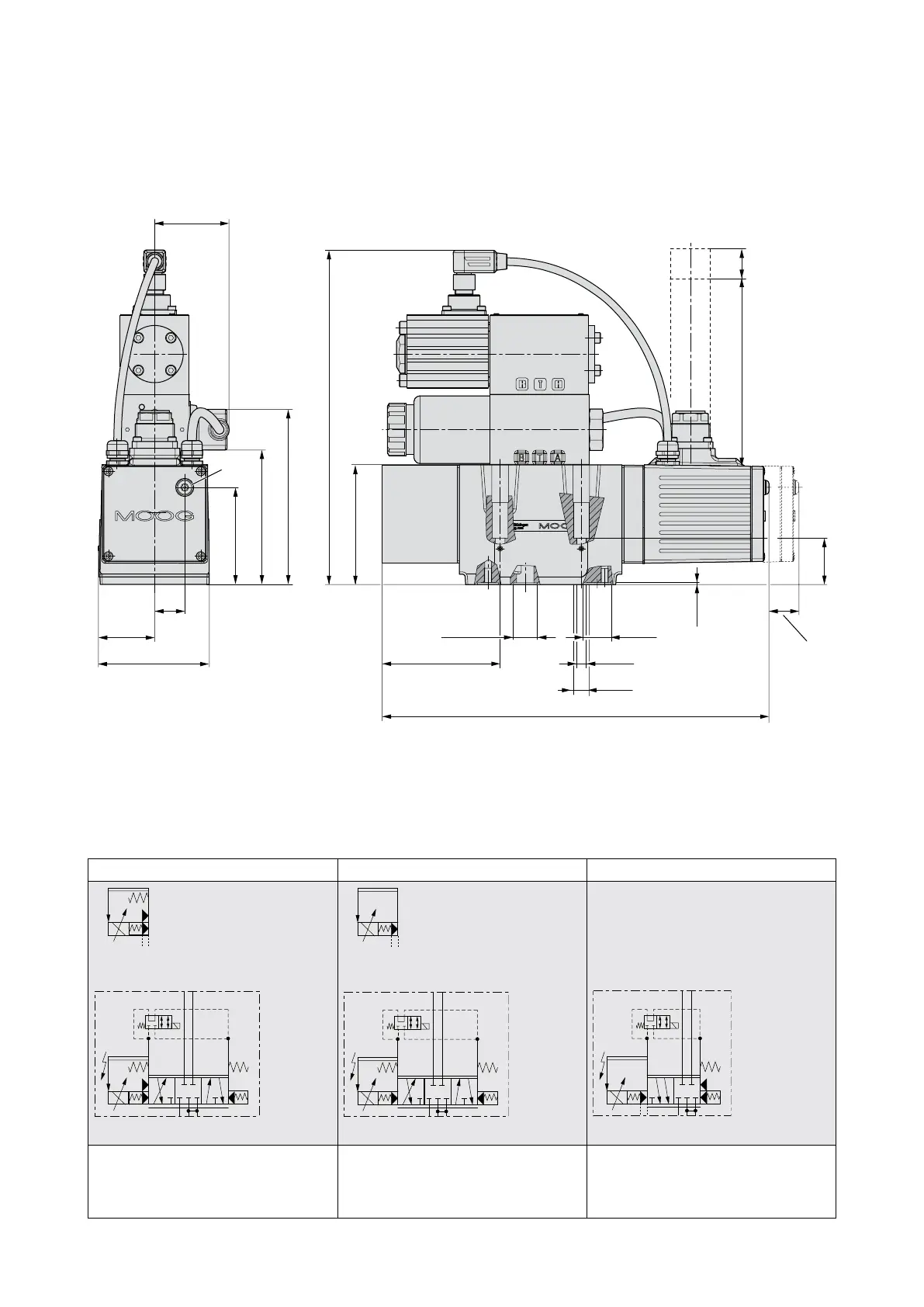
Installation Drawing for Fail-safe Options U and W
1
X Y
11+PE
(6+PE)
2
20
(0.79)
21
(0.83)
37.4
(1.47)
74
(2.91)
64.5
(2.54)
89.4
(3.52)
117
(4.61)
223
(8.78)
79.6
(3.13)
31
(1.22)
1.3
(0.05)
15.7
(0.62)
6 x ø
6.4
(0.25)
ø
10.5
(0.41)
ø
18.7
(0.74)
ø
78.5
(3.09)
258
(10.16)
55.5
(2.19)
Mating connector Headroom for
disconnecting
20
(0.79)
125
(4.92)
[85]
[(3.35)]
1 Electric null adjust (behind screw plug)
Attention! Electric null adjust is not possible if the position of the main spool is monitored!
2 With dampening plate
Optional X and Y external Optional X and Y external Only X and Y external
T TP
YX
BA
1
T TP
YX
BA
1
TTPYX
1
Fail-safe option U
4-way design
Fail-safe position P → B and defined
center position
Fail-safe option W
4-way design
Defined center position
Fail-safe option W
2x2-way design
Defined center position
Flow direction only according to symbol