20Rev. C, April 2017
TECHNICAL DATA Moog D680 Series Proportional Control Valves
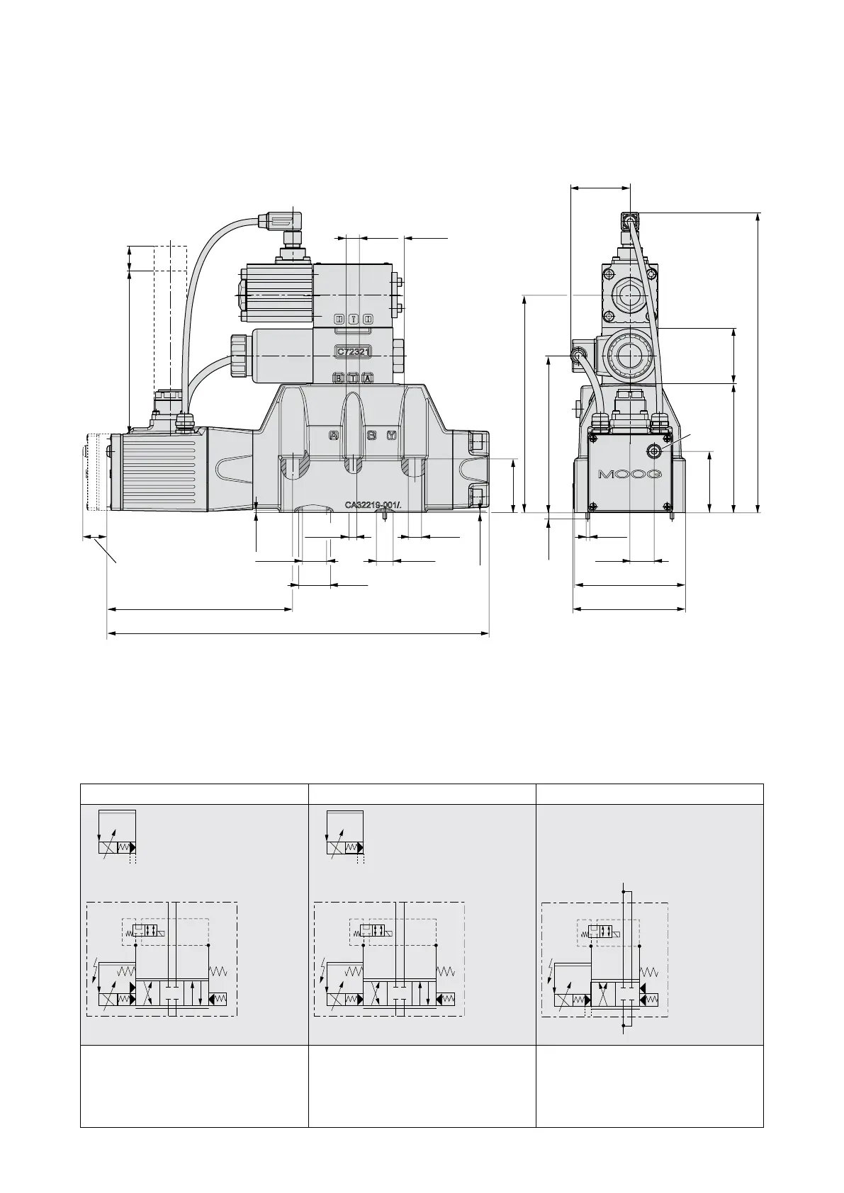
SIZE 07 - D682 PROPORTIONAL VALVE
20
TECHNICAL DATA
Rev. C, April 2017
Moog D680 Series Proportional Control Valves
SIZE 07 - D682 PROPORTIONAL VALVE
Installation Drawing for Fail-safe Options U and W
1
X,Y
11+PE
(6+PE)
2
51
(2.01)
107
(4.21)
181
(7.13)
130.2
(5.13)
46.5
(1.83)
253
(9.96)
44.5
(1.75)
5
(0.20)
55.5
(2.19)
3
(0.12)
ø
20
(0.79)
92
(3.62)
94
(3.68)
11
(0.43)
ø
18
(0.71)
ø
11
(0.43)
ø
6.5
(0.26)
ø
13.9
(0.55)
ø
20
(0.79)
ø
26.5
(1.04)
ø
154
(6.06)
317
(12.48)
1.3
(0.05)
2
(0.08)
Mating connector
Headroom for
disconnecting
20
(0.79)
125
(4.92)
[85]
[(3.35)]
21
(0.83)
1 Electric null adjust (behind screw plug)
Attention! Electric null adjust is not possible if the position of the main spool is monitored!
2 With dampening plate
Optional X and Y external Optional X and Y external Only X and Y external
TP
YX
BA
TP
YX
BA
TPYX
BA
Fail-safe option U
4-way design
Fail-safe position P → B and defined
center position
Fail-safe option W
4-way design
Defined center position
Fail-safe option W
2x2-way design
Defined center position by mechanical
spool stop
Flow direction only according to symbol
1 Electric null adjust (behind screw plug)
Attention! Electric null adjust is not possible if the position of the main spool is monitored!
2 With dampening plate