37Rev. C, April 2017
TECHNICAL DATA Moog D680 Series Proportional Control Valves
SIZE 10 - D685 PROPORTIONAL VALVE
37
TECHNICAL DATA
Rev. C, April 2017
Moog D680 Series Proportional Control Valves
SIZE 10 - D685 PROPORTIONAL VALVE
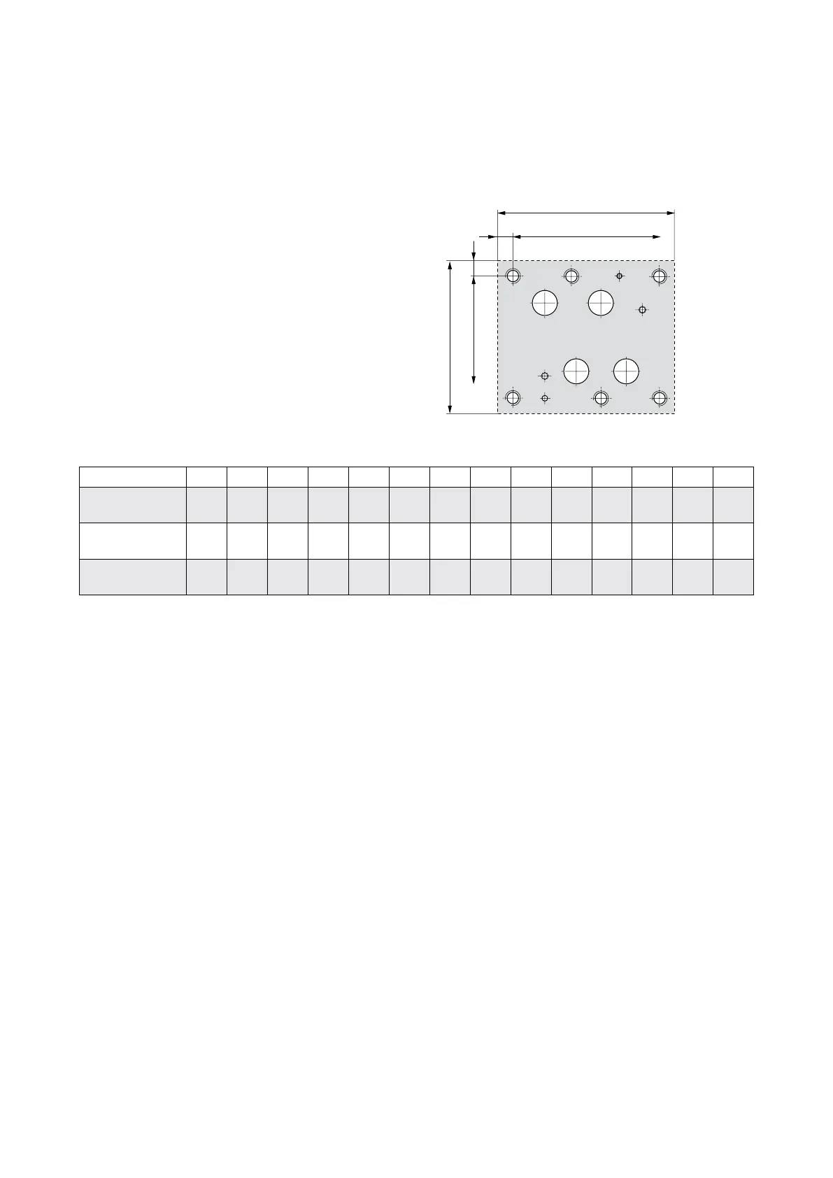
Hole Pattern of Mounting Surface
The mounting manifold must conform to
ISO 4401-10-09-0-05.
• For a maximum flow rate, the ports P, T, A and B should
be provided with a diameter of 50 mm (1.97 in) (not
according to standard).
• Flatness of mounting surface < 0.01 mm (0.0004 in)
over a distance of 100 mm (3.94 in).
• Mean roughness R
a
better than 0.8 µm (0.0000314 in).
Designation P A B T X Y F
1
F
2
F
3
F
4
F
5
F
6
G
1
1)
G
2
Size Ø mm
in
50
1.97
50
1.97
50
1.97
50
1.97
11.2
0.44
11.2
0.44
M20
M20
M20
M20
M20
M20
M20
M20
M20
M20
M20
M20
7.5
0.3
7.5
0.3
Position X mm
in
114.3
4.5
82.5
3.248
147.6
5.811
41.3
1.626
41.3
1.626
168.3
6.626
0
0
190.5
7.5
190.5
7.5
0
0
76.2
3
114.3
4.5
147.6
5.811
41.3
1.626
Position Y mm
in
35
1.378
123.8
4.874
123.8
4.874
35
1.378
130.2
5.126
44.5
1.752
0
0
0
0
158.8
6.252
158.8
6.252
0
0
158.8
6.252
0
0
158.8
6.252
x
y
F
1
F
2
F
5
G
1
F
3
F
6
F
4
G
X
2
PT
Y
A B
(9.06)
20
(0.79)
(7.99)
22
(0.87)
1) Dimension not according to ISO 4401 but DIN 24340-2. The position of the mounted safety pin is according to EN
standard. Hole G
1
according to ISO 4401 is at 138.6 mm (5.46 in) and it is additionally drilled in the valve body in line
with ISO 4401.