6Rev. C, April 2017
INTRODUCTION Moog D680 Series Proportional Control Valves
DESCRIPTION OF OPERATION
6
INTRODUCTION
Rev. C, April 2017
Moog D680 Series Proportional Control Valves
DESCRIPTION OF OPERATION
Proportional Control Valves
Functional Description of the Direct Drive Pilot
Valve D633
The pilot valve is a 4/3-way servo valve that is driven by
a linear force motor. The linear force motor consists of a
coil, permanent magnets, pole pieces, an armature and a
centering spring. The armature of the linear force motor
is linked to a spool that moves in a bushing inside the pilot
valve housing. The spool controls the flow from the pilot
pressure port to the control chambers of the main stage
spool.
The de-energized position of the pilot valve’s spool is
determined by the centering springs of the linear force
motor. If a PWM current is applied to the coil of the
linear force motor, an electromagnetic field is created
that superimposes the magnetic field of the permanent
magnets. This creates a force on the armature, which
causes the armature and thus the pilot valve’s spool
to be displaced. The direction of the displacement
depends on the polarity of the current that is applied.
The displacement of the centering spring causes a spring
force opposing the direction of movement. Thus, the
displacement of the pilot valve’s spool is approximately
proportional to the applied PWM current.
In the center position, which is defined by the centering
spring, the linear force motor does not consume any
current. This leads to a low energy consumption if the
main stage spool is held at a constant position or during
standby periods.
Biased Pilot Valve D633
A biased pilot valve means that the spring centered
position of the pilot valve is outside the center position.
For D633 pilot valves, this means that in a spring-centered
position the pilot valve is about 10 to 20 % opened in
either direction P → A or in direction P → B. This design
is used to move the main stage spool to a defined end
position if the electronic supply fails or is switched off and
the pilot supply is still active.
Biased pilot valves are used for all fail-safe functions
where the main stage spool position is not in the center
position in a failure situation. If the desired spool position
in case of a failure is the center position, an unbiased pilot
valve in combination with a 4/2-way solenoid valve has
to be used. Please refer to the section „Applications with
Safety Requirements (Fail-safe)“ for further details on the
different fail-safe options.
A biased D633 pilot valve has a rated flow that is about
25 % lower than that of an unbiased D633 pilot valve.
Hence, the step response times for Moog D682 to D684
Series Proportional Control Valves with biased pilot valves
are slightly slower than with unbiased pilot valves. The
different dynamic characteristics of valves with biased
and unbiased pilot valves are shown in the technical data
section for each valve size.
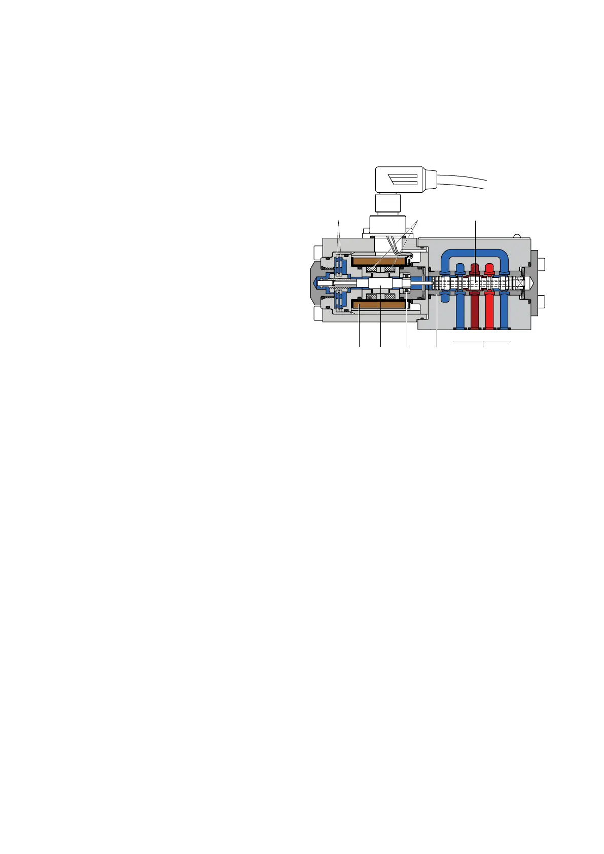
D633 Pilot Valve
T
V
B
V
P
V
A
V
1 2 3
45678
1 Centering springs
2 Permanent magnets
3 Spool
4 Ports
5 Bushing
6 Bearing
7 Armature
8 Coil