EasyManua.ls Logo

Mooney M20K - Page 141

Mooney M20K
437 pages
Print Icon
To Next Page IconTo Next Page
To Previous Page IconTo Previous Page
Loading...
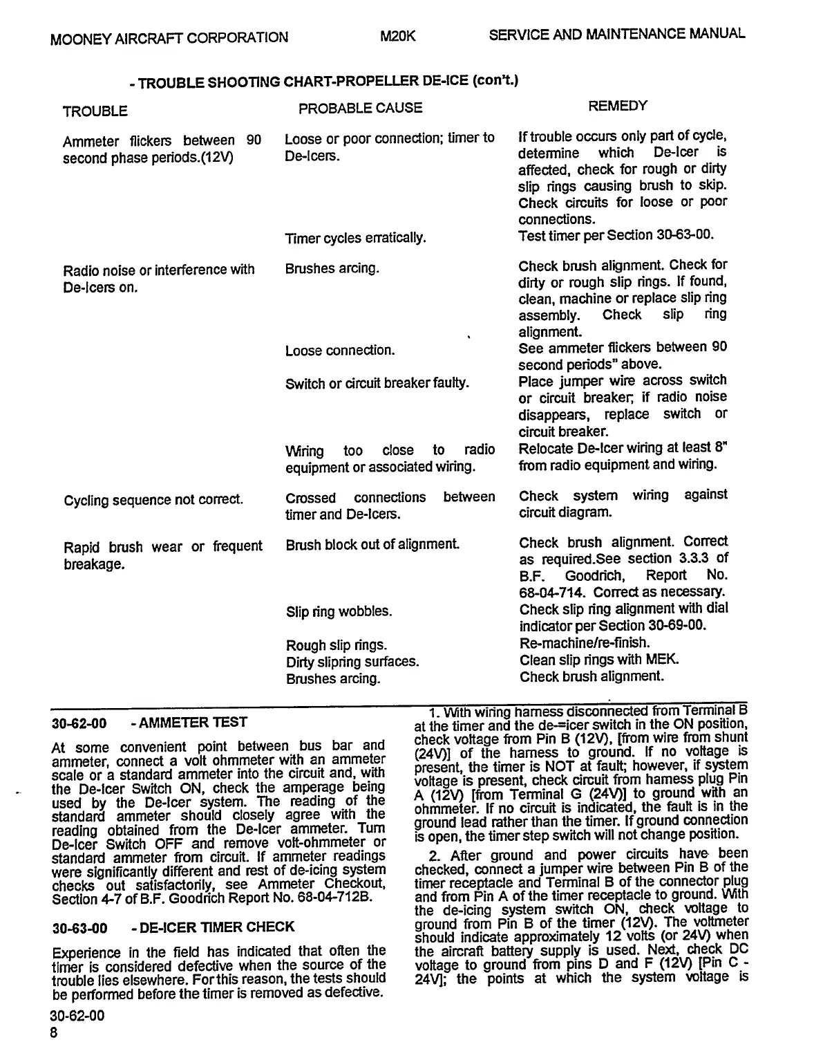
MOONEY
AIRCRAFT
CORPORATION
M20K
SERVICE
AND
MAINTENANCE
MANUAL
TROUBLE
SHOOTTNG
CHART-PROPELLER
DE-ICE
(conY.)
TROUBLE
PROBABLE
CAUSE
REMEDY
Ammeter
flickers
between
90
Loose
or
poor
connection;
timer
to
If
trouble
occurs
only
part
of
cycle,
second
phase
peniods.(l2V)
De-lcew.
detemnine
which
De-leer
is
affected,
check
for
rough
or
dirty
slip
n’ngs
causing
brush
to
skip.
Check
circuits
for
loose
or
poor
connections.
Timer
cycles
erratically.
Test
timer
per
Section
30-63-00.
Radio
noise
or
interference
with
Brushes
arcing.
Check
brush
alignment.
Check
for
De-leers
on,
dirty
or
rough
slip
n’ngs.
If
found,
clean,
machine
or
replace
slip
ring
assembly.
Check
slip
ring
alignment.
Loose
connection.
See
ammeter
flickers
between
90
second
periods"
above.
Switch
or
circuit
breaker
faulty.
Place
jumper
wire
across
switch
or
circuit
breaker;
if
radio
noise
disappears,
replace
switch
or
circuit
breaker.
Win’ng
too
close
to
radio
Relocate
De-leer
wiring
at
least
8"
equipment
or
associated
wiring.
From
radio
equipment
and
wiring.
Cycling
sequence
not
cor~-ect.
Crossed
connections
between
Check
system
wiring
against
timer
and
De-leers.
circuit
diagram.
Rapid
brush
wear
or
frequent
Brush
block
out
ofalignment.
Check
brush
alignment.
Correct
breakage,
as
required.See
section
3.33
of
B.F.
Goodn’ch,
Report
No.
68-04-714.
Correct
as
necessary.
Slip
ring
wobbles.
Check
slip
n’ng
alignment
with
dial
indicator
per
Section
30-69-00.
Rough
slip
n’ngs.
Re-machine/re-finish.
Dirty
slipring
surfaces.
Clean
slip
n’ngs
with
MEK.
Brushes
arcing.
Check
brush
alignment.
i.
With
winng
harness
disconnected
from
Terminal
a
30-62-00
-AMMETER
TEST
at
the
timer
and
the
de-=icer
switch
in
the
ON
position,
At
some
convenient
point
between
bus
bar
and
check
voltage
from
Pin
B
(12V),
Ifrom
wire
from
shunt
ammeter,
connect
a
volt
ohmmeter
with
an
ammeter
(24Vll
of
the
harness
to
ground.
If
no
voltage
is
scale
or
a
standard
ammeter
into
the
circuit
and,
with
present,
the
timer
is
NOT
at
fault;
however,
if
system
the
De-leer
Switch
ON,
check
the
amperage
being
voltage
is
present,
check
circuit
from
hamess
plug
Pin
used
by
the
De-leer
system.
The
reading
of
the
A
(12V)
[from
Terminal
G
(24Vll
to
ground
with
an
standarCI
ammeter
should
closely
agree
with
the
ohmmeter.
If
no
circuit
is
indicated,
the
fault
is
in
the
reading
obtained
from
the
De-leer
ammeter.
Tum
ground
lead
rather
than
the
timer.
If
ground
connection
De-leer
Switch
OFF
and
remove
volt-ohmmeter
or
is
open,
the
timer
step
switch
will
not
change
position.
standard
ammeter
from
circuit.
If
ammeter
readings
2.
After
ground
and
power
circuits
have
been
were
significantly
different
and
rest
of
de-icing
system
checked,
connect
a
jumper
wire
between
Pin
B
of
the
checks
out
satisfacton’ly,
see
Ammeter
Checkout,
timer
receptacle
and
Terminal
B
of
the
connector
plug
Section
67
of
B.F.
Goodn’ch
Report
No.
68-04-7126.
and
from
Pin
A
of
the
timer
receptacle
to
ground.
With
the
de-icing
system
switch
ON,
check
voltage
to
30-63-00
DE-ICER
TIMER
CHECK
ground
from
Pin
B
of
the
timer
(12V).
The
voltmeter
should
indicate
approximately
12
volts
(or
24V)
when
Experience
in
the
field
has
indicated
that
often
the
the
aircraft
battery
supply
is
used.
Ne~,
check
DC
timer
is
considered
defective
when
the
source
of
the
voltage
to
ground
from
pins
D
and
F
(12V)
[Pin
C
trouble
lies
elsewhere.
Forthis
reason,
the
tests
should
24V];
the
points
at
which
the
system
voltage
is
be
performed
before
the
timer
is
removed
as
defective.
30-62-00
OLDWILLWAYNE

Table of Contents