EasyManua.ls Logo

Mooney M20K - System Rigging

Mooney M20K
437 pages
Print Icon
To Next Page IconTo Next Page
To Previous Page IconTo Previous Page
Loading...
MOONEY
AIRCRAFT
CORPORATION
M20K
SERVICE
AND
MAINTENANCE
MANUAL
lcS~’
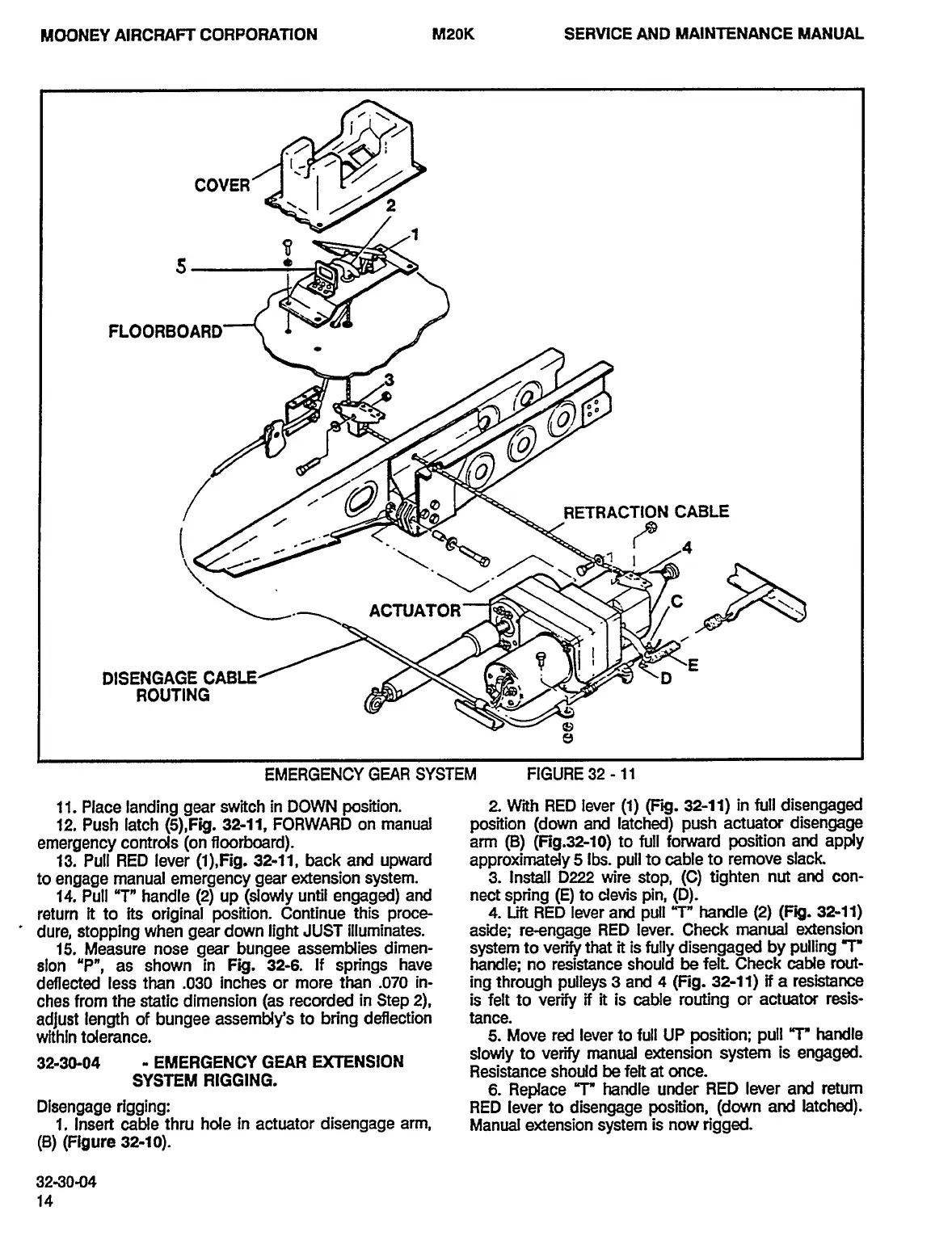
COVER
,:i
2
FLOORBOARD
~b.
RETRACTION
CABLE
ACTUATOR
I
I
DISENGAGE
CABLE
D
ROUTING
EMERGENCY
GEAR
SYSTEM
FIGURE
32
11
11.
Place
landing
gear
switch
in
DOWN
position.
2
With
RED
lever
(1)
(Fig.
32-11)
in
full
disengaged
12.
Push
latch
O),Fig.
32-11,
FORWARD
on
manual
position
(down
and
latched)
push
actuator
disengage
emergency
controls
ton
ffoorboard).
arm
(5)
(Fig.32-10)
to
full
forward
position
and
apply
13.
Pull
RED
lever
(1),Fig.
32-11,
back
and
upward
approximately
5
Ibs.
pull
to
cable
to
remove
slack
to
engage
manual
emergency
gear
e>ctension
system.
3.
Install
D222
wire
stop,
(C)
tighten
nut
and
con-
14.
Pull
"T"
handle
(2)
up
(slowly
until
engaged)
and
nect
spn’ng
(5)
to
devis
pin,
(D).
return
it
to
its
original
position.
Continue
this
proce-
4.Lift
RED
lever
and
pull
r"
handle
(2)
(Fig.
32-11)
dure,
stopping
when
gear
down
light
JUST
illuminates.
aside;
re-engage
RED
lever.
Check
manual
extension
15.
Measure
nose
gear
bungee
assemblies
dimen-
system
to
verify
that
it
is
fully
disengaged
by
pulling
T
sion
"P",
as
shown
in
Fig.
32-6.
If
spn’ngs
have
handle;
no
resistance
should
be
felt
Check
cable
rout-
deflected
less
than
.030
inches
or
more
than
.070
in-
ing
through
pulleys
3
and
4
(Fig.
32-11)
if
a
resistance
ches
from
the
static
dimension
las
recorded
in
Step
2),
is
felt
to
verify
if
it
is
cable
routing
or
actuator
resis-
adjust
length
of
bungee
assembly’s
to
bn’ng
deflection
tance.
within
tolerance.
5.
Move
red
lever
to
full
UP
position;
pull
r"
handle
32-30-04
EMERGENCY
GEAR
UC~NSION
slowly
to
verify
manual
e~ctension
system
is
engaged.
Resistance
should
be
felt
at
once.
SYSTEM
RIGGING.
6.
Replace
r"
handle
under
RED
lever
and
return
Dlsengage
rigging:
RED
lever
to
disengage
position,
(down
and
latched).
1,
Insert
cable
thru
hole
in
actuator
disengage
arm,
Manual
extension
system
is
now
ngged.
(B)
(Figure
32-10).
32-30-04
OLDWILLWAYNE

Table of Contents