EasyManua.ls Logo

Mooney M20K - Page 157

Mooney M20K
437 pages
Print Icon
To Next Page IconTo Next Page
To Previous Page IconTo Previous Page
Loading...
SERVICE
AND
MAINTENANCE
MANUAL
M20K
MOONEY
AIRCRAFT
CORPORATION
34.
Read
torque
wrench
value
at
the
UV\CT
me
32-3093
NOSE
LANDING
GEAR
RIGGING
ment
shtm
stock
pulls
loose.
PROCEDURE
(25´•10001hru
25TBA)
35.
Repeat
steps
30
through
34
on
other
main
land-
1.
Check
eccentn’c
bushings
(J),
Fig.32-4,
on
gear
ing
gear
leg,
truss
assy.
to
be
installed
with
bolt
hole
in
upper
for-
36.
Use
adjusting
nuts
(Y)
on
retract
tubes
01)
to
,,d
position.
equalize
breakaway
torque
values
within
10.0
inch
Ibs.
2
Adjust
nose
gear
retraction
tubes
(F),
Fig.
32-3,
Adjust
torque
to
250
to
280
inch
Ibs.
so
they
can
be
reconnected
to
main
retraction
37.
Tum
Master
Switch
ON.
bellcrank
with
zero
preload.
38.
RUN
GEAR
DOWN
ELECTRICALLY
AND
CHECK
THAT
TORQUE
VALUES
DO
NOT
U(CEED
325
INCH
NOTE
POUNDS
USING
TORQUE
WRENCH/SHIM
STOCK
The
eccentric
bushings
may
require
rotation
to
a
METHOD.
new
position
in
order
to
meet
zero
preload
condition.
LANDING
GEAR
WARNING
ADJUSTMENT
3.
Measure
nose
gear
bungees
dimension
(P),
Fig.
1.
Check
that
landing
gear
waming
light
circuit
32-6,
and
record
for
future
reference.
breaker
is
pushed
IN.
4.
Push
landing
gear
actuator
C/B
IN
2.
Check
that
landing
gear
actuator
circuit
breaker
is
5.
Place
landing
gear
switch
in
UP
position.
pulled
OUT.
6.
Turn
Master
Switch
ON.
3.
Turn
Master
switch
ON.
7.
Push
RED
GEAR
SAFETY
BYPASS
SWITCH
IN;
4.
Set
DOWN
limit
switch
striker
arm
(J),
(Fig.
32-5),
hold
it
IN
to
partially
retract
the
landing
gear;
release
so
gear
down
limit
switch
is
just
CLOSED
and
the
switch.
GREEN
GEAR
DOWN
light
is
ON.
Secure
striker
arm
in
8.
Turn
Master
switch
OFF.
position.
9.
Pull
landing
gear
actuator
C/B
OUT.
5.
Turn
Master
Switch
OFF.
in.
Screw
each
nose
gear
retraction
tube
(F)
The
main
landing
gear
system
is
now
n’gged
for
the
(Fig.32-3)
IN
(clockwise
looking
toward
front
of
the
aircraft)
one
(1)
full
turn,
then
reattach
to
main
retrac-
gear
down
and
locked
condition,
tion
bellcrank.
A
FJ
I
I
B
FUS.
STA.
33.0
1
DETATL
B
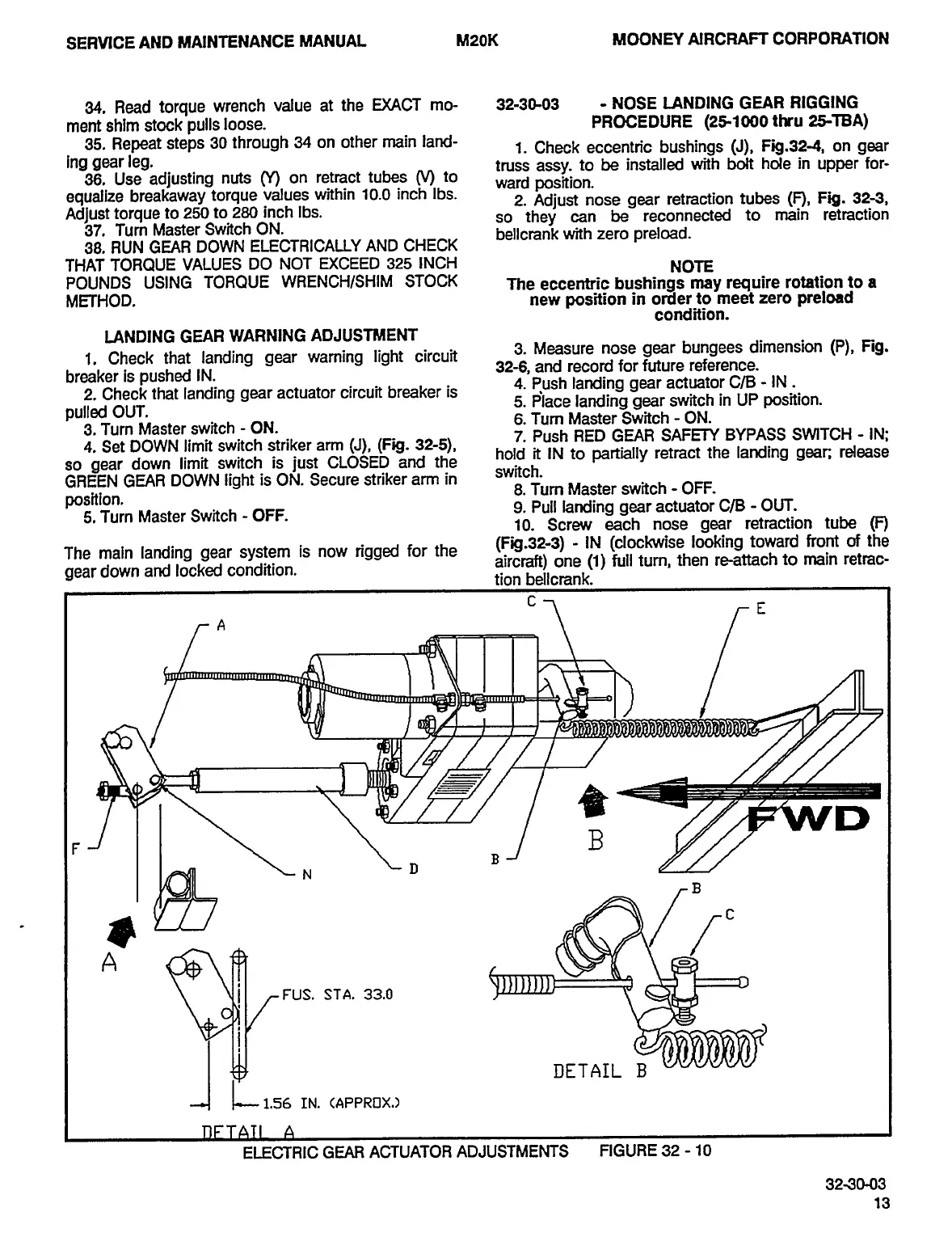
ELECTRIC
GEAR
ACTUATOR
ADJUSTMENTS
FIGURE
32
10
3290-03
13
OLDWILLWAYNE

Table of Contents