EasyManua.ls Logo

Mooney M20K - Landing Gear Actuator Clutch

Mooney M20K
437 pages
Print Icon
To Next Page IconTo Next Page
To Previous Page IconTo Previous Page
Loading...
SERVICE
AND
MAINTENANCE
MANUAL
M20K
MOONC/
AIRCRAFT
CORPORATION
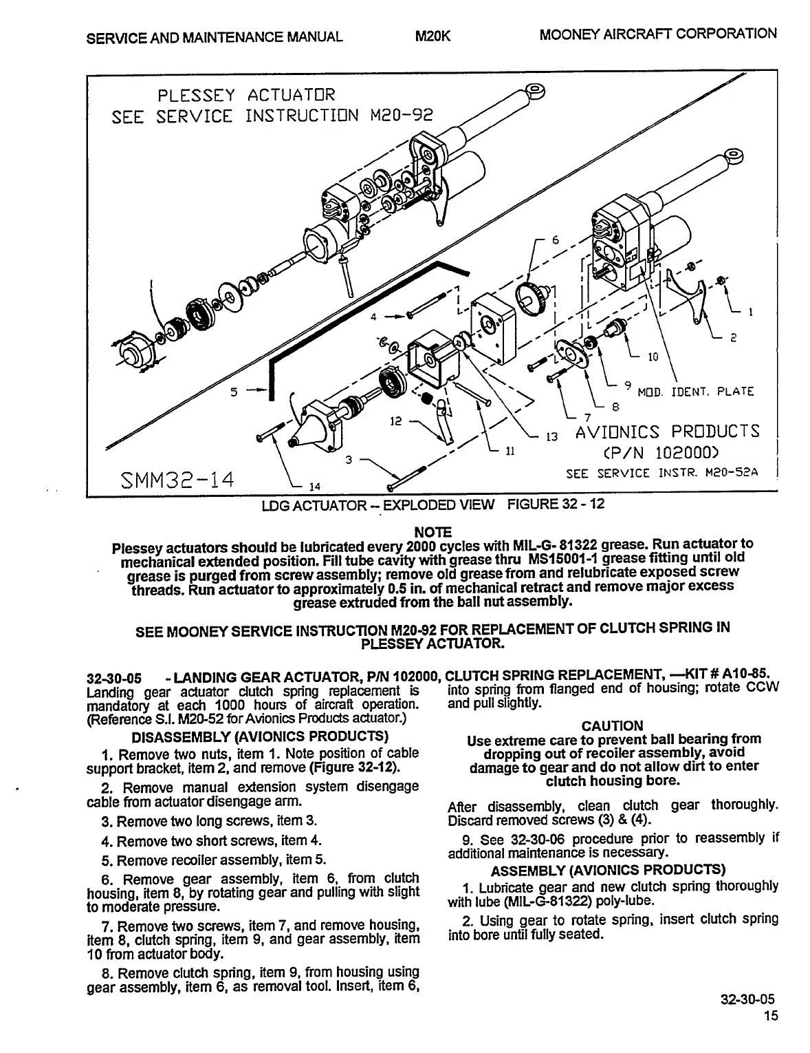
PLESSEY
ACTUATOR
SEE
SERVICE
INSTRUCTION
M20-92
6
r
I1~
1Y
iC
i,
i
2
~v
18~
5
i’,
9
MOD.
IDENT.
PLATE
SMM32-14
*i~
L
11
(P/N
102000>
13
AVIONICS
PRODUCTS
SEE
SERVICE
INSTR.
M20-52A
LDG
ACTUATOR
U(PLODED
VIEW
FIGURE
32
12
NOTE
Plessey
actuators
should
be
lubricated
every
2000
cycles
with
M1L-G-
81322
grease.
Run
actuator
to
mechanical
extended
position.
Fill
tube
cavity
with
grease
thru
MS15001-1
grease
fitting
until
old
grease
is
purged
from
screw
assembly;
remove
old
grease
from
and
relubricate
exposed
screw
threads.
Run
actuator
to
approximately
0.5
in.
of
mechanical
retract
and
remove
major
excess
grease
extruded
from
the
ball
nut
assembly.
SEE
MOONN
SERVICE
INSTRUCTION
M20-92
FOR
REPLACEMENT
OF
CLUTCH
SPRING
IN
PLESSC/
ACTUATOR.
3230-05
LANDING
GEAR
ACTUATOR,
P/N
102000,
CLUTCH
SPRING
REPLACEMENT,
--KIT
Al
0-85.
Landing
gear
actuator
clutch
spn’ng
replacement
is
into
spn’ng
from
flanged
end
of
housing;
rotate
CCW
mandatory
at
each
1000
hours
of
aircraft
operation.
and
pullslightly.
(Reference
S.I.
M20-52
forAvionics
Products
actuator.)
CAUTION
DISASSEMBLY
(AVIONICS
PRODUCTS)
Use
extreme
care
to
prevent
ball
bearing
from
i.
Remove
two
nuts,
item
1.
Note
position
of
cable
dropping
out
of
recoiler
assembly,
avoid
support
bracket,
item
2,
and
remove
(Figure
32-12).
damage
to
gear
and
do
not
allow
dirt
to
enter
2.
Remove
manual
e>dension
system
disengage
clutch
housing
bore.
cable
from
actuator
disengage
arm.
After
disassembly,
clean
clutch
gear
thoroughly.
3.
Remove
two
long
screws,
item
3.
Discard
removed
screws
(3)
8
(4).
4.
Remove
two
short
screws,
item
4.
9.
See
32-30-06
procedure
prior
to
reassembly
if
5.
Remove
recoiler
assembly,
item
5.
additional
maintenance
is
necessary.
ASSEMBLY
(AVIONICS
PRODUCTS)
6.
Remove
gear
assembly,
item
6,
from
clutch
housing,
item
8,by
rotating
gear
and
pulling
with
slight
1.
Lubn’cate
gear
and
new
clutch
spring
thoroughly
to
moderate
pressure,
with
lube
(MIl-E81322)
poly-lube.
7.
Remove
two
screws,
item
7,
and
remove
housing,
2.
Using
gear
to
rotate
spring,
insert
clutch
spring
item
8,
clutch
spn’ng,
item
9,
and
gear
assembly,
item
into
bore
until
fully
seated.
10
from
actuator
body.
8.
Remove
clutch
spring
item
9,
from
housing
using
gear
assembly,
item
6,
as
removal
tool.
Insert,
item
6,
32-30-05
15
OLDWILLWAYNE

Table of Contents