EasyManua.ls Logo

Mooney M20K - Page 144

Mooney M20K
437 pages
Print Icon
To Next Page IconTo Next Page
To Previous Page IconTo Previous Page
Loading...
SERVICE
AND
MAINTENANCE
MANUAL
M20K
MOONN
AIRCRAFT
CORPORATION
B~P,
~PI
~I
SM30-4
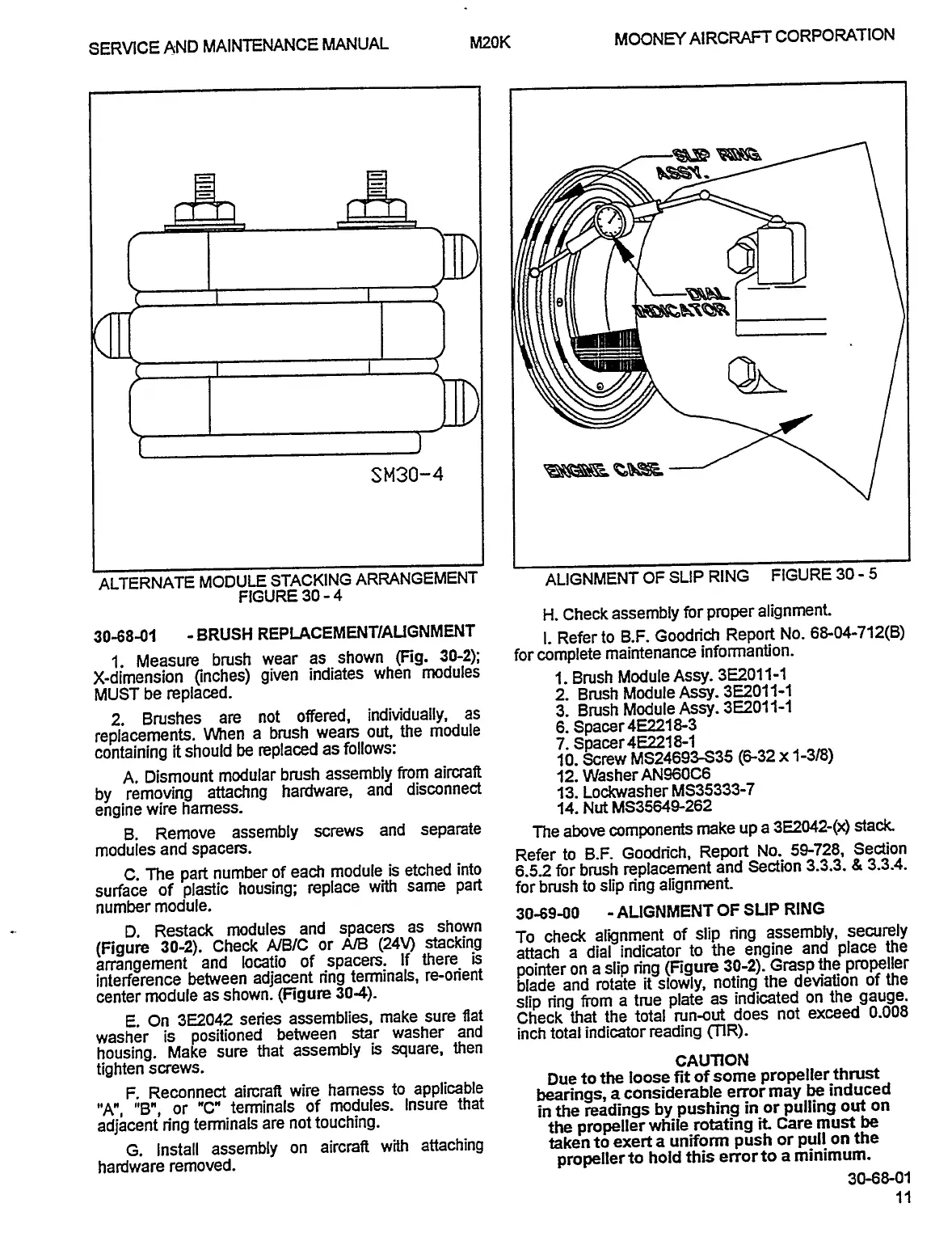
ALTERNATE
MODULE
STACKING
ARRANGEMENT
ALIGNMENT
OF
SLIP
RING
FIGURE
30
5
FIGURE
30
4
H.
Check
assembly
for
proper
alignment.
30-68-01
BRUSH
REP
LACEMENTIAUGNMENT
i.
Refer
to
B.F.
Goodrich
Report
No.
6&04-712(8)
1.
Measure
brush
wear
as
shown
(Fig.
30-2);
for
complete
maintenance
informantion.
X-dimension
(inches)
given
indiates
when
modules
1.Brush
Module
Assy.
3E2011-1
MUST
be
replaced.
2.
Brush
Module
Assy.
382011-1
2.
Brushes
are
not
offered,
individually,
as
3.
BNsh
Module
Assy.
382011-1
replacements.
When
a
brush
wears
out,
the
module
6.
Spacer4E2218-3
containing
it
should
be
replaced
as
follows:
7.
Spacer4E2218-1
10.
Screw
MS24693S35
~-32
x
1-3/8)
A.
Dismount
modular
brush
assembly
from
aircraft
12.
WasherAN960CG
by
removing
attachng
hardware,
and
disconnect
13.
Lockwasher
MS35333-7
engine
wire
harness.
14.
Nut
MS35649-262
B.
Remove
assembly
screws
and
separate
The
above
components
make
up
a
3E2042-Q
stack
modules
and
spacers.
Refer
to
B.F.
Goodn’ch,
Report
No.
59-728,
Section
C.
The
part
number
of
each
module
is
etched
into
6.52
for
brush
replacement
and
Section
3.3.3.
8
3.3.4.
surface
of
plastic
housing;
replace
with
same
part
for
brush
to
slip
ring
alignment.
number
module.
30-69-00
ALIGNMENT
OF
SUP
RING
D.
Restack
modules
and
spacers
as
shown
(Figure
30-2).
Check
AIB/C
or
A/B
(24V)
stacking
To
check
alignment
of
slip
n’ng
assembly,
securely
arrangement
and
locatio
of
spacers.
If
there
is
attach
a
dial
indicator
to
the
engine
and
place
the
interference
between
adjacent
n’ng
terminals,
re-orient
pointer
on
a
slip
n’ng
(Figure
30-2).
Grasp
the
propeller
blade
and
rotate
it
slowly,
noting
the
deviation
of
the
center
module
as
shown.
(Figure
30-4).
slip
ring
from
a
tiue
plate
as
indicated
on
the
gauge.
E.
On
382042
series
assemblies,
make
sure
fiat
Check
that
the
total
run-out
does
not
exceed
0.008
washer
is
positioned
between
star
washer
and
inch
total
indicator
reading
CLlR).
housing.
Make
sure
that
assembly
b
square,
then
CAUTION
tighten
screuvs.
Due
to
the
loose
fit
of
some
propeller
thntst
F.
Reconnect
aircraft
wire
harness
to
applicable
bearings,
a
considerable
error
may
be
induced
"A",
"B",
or
"C"
terminals
of
modules.
Insure
that
i,
the
readings
by
pushing
in
or
pulling
out
on
adjacent
n’ng
terminals
are
not
touching.
the
propeller
while
rotating
it.
Care
must
be
G.
Install
assembly
on
aircraft
with
attacfiing
taken
to
exert
a
uniform
push
or
pull
on
the
hardware
removed.
propeller
to
hold
this
error
to
a
minimum.
30-6&01
OLDWILLWAYNE

Table of Contents