EasyManua.ls Logo

Mooney M20K - Avionics Equipment; Engine Instruments and Circuit Breakers

Mooney M20K
437 pages
Print Icon
To Next Page IconTo Next Page
To Previous Page IconTo Previous Page
Loading...
MOONEY
AIRCRAFT
CORPORATION
M20K
SERVICE
AND
MAINTENANCE
MANUAL
C.
Connect
post
lights.
D.
Connect
all
plumbing
and/or
electrical
connec-
tions
to
instrument;
perform
pitot-static
leak
check.
E.
Position
glareshield
so
electrical
connections
can
be
made
and
secured.
F.
C
Secure
glareshield
and
cover
plate
with
screws.
39-10-02
-AVIONICS
EQUIPMENT
I
rB
Each
avionics
package
installed
is
basically
a
cus-
tomized
package
to
meet
the
requirements
of
the
cus-
tomer.
Wiring
harness,
any
associated
plumbing
or
I
Flooli
mechanical
mechanisms
required
for
a
particular
avionics
installation
are
well
secured
to
prevent
any
in-
terference
with
other
components.
Removal
of
these
avionics
components
will
require
evaluation
of
each
in-
CIRCUIT
stallation
to
determine
proper
procedure
or
sequence
to
follow.
O
1.
Removal.
PANEL
Li
Most
individual
avionics
components
are
mounted
in
o
o
E
slide
out
chassis
racks.
Loosen
screw
on
the
face
of
component
and
slide
unit
straight
aft
to
remove.
Some
components
are
not
mounted
in
slide
out
chas-
sis.
Removal
of
these
units
will
require
same
sequence
as
removal
of
flight
instruments
in
Section
39-10-01.
CAUTION
Radio
panel
must
be
stacked
from
the
bottom
to
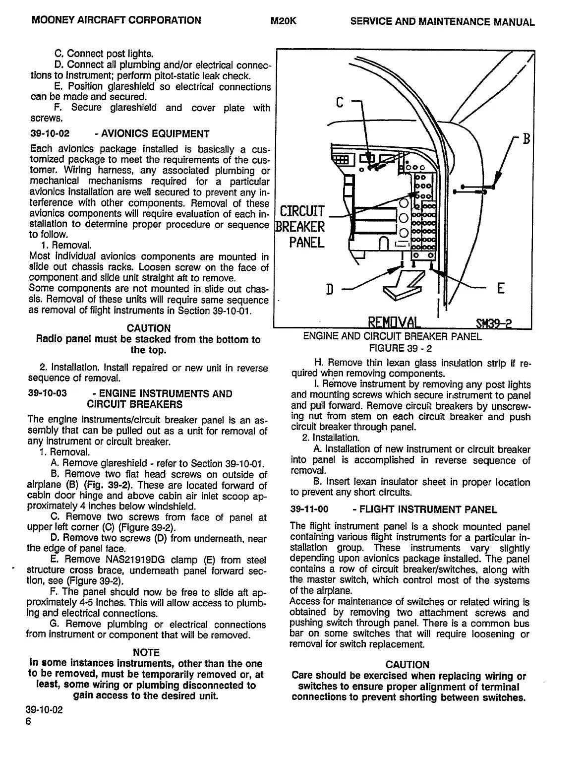
ENGINE
AND
CIRCUIT
BREAKER
PANEL
the
top.
FIGURE
39
2
2.
Installation.
Install
repaired
or
new
unit
in
reverse
H.
Remove
thin
lexan
glass
insulation
strip
if
re-
sequence
of
removal.
quired
when
removing
components.
I.
Remove
instrument
by
removing
any
post
lights
39-10-03
ENGINE
INSTRUMENTS
AND
and
mounting
screws
which
secure
irlstrument
to
panel
CIRCUIT
BREAKERS
and
pull
forward.
Remove
circuit
breakers
by
unscrew-
The
engine
instruments/circuit
breaker
panel
is
an
as-
i"g
"Ut
from
stem
on
each
circuit
breaker
and
push
sembly
that
can
be
pulled
out
as
a
unit
for
removal
of
circuit
breaker
through
panel.
any
instrument
or
circuit
breaker.
2.
Installation.
1.
Removal.
A.
Installation
of
new
instrument
or
circuit
breaker
A.
Remove
glareshield
refer
to
Section
39-10-01.
i"to
panel
is
accomplished
in
reverse
sequence
of
B.
Remove
two
flat
head
screws
on
outside
of
’emoval.
airplane
(B)
(Fig.
39-2).
These
are
located
forward
of
B.
Insert
lexan
insulator
sheet
in
proper
location
to
prevent
any
short
circuits.
cabin
door
hinge
and
above
cabin
air
inlet
scoop
ap-
proximately
4
inches
below
windshield.
39-11-00
FLIGHT
INSTRUMENT
PANEL
C.
Remove
two
screws
from
face
of
panel
at
upper
left
corner
(C)
(Figure
39-2).
The
Right
instrument
panel
is
a
shock
mounted
panel
D.
Remove
two
screws
(D)
from
underneath,
near
containing
various
Right
instruments
for
a
particular
in-
the
edge
of
panel
face.
stallation
group.
These
instruments
vary
slightly
E.
Remove
NAS21919DG
clamp
(E)
from
steel
depending
upon
avionics
package
installed.
The
panel
structure
cross
brace,
underneath
panel
forward
sec-
co"tains
a
row
of
circuit
breaker/switches,
along
with
tion,
see
(Figure
39-2).
the
master
switch,
which
control
most
of
the
systems
F.
The
panel
should
now
be
free
to
slide
aft
ap-
of
the
airplane.
proximately
4-5
inches.
This
will
allow
access
to
plumb-
Access
for
maintenance
of
s~Yitches
or
related
wiring
is
ing
and
electrical
connections.
obtained
by
removing
two
attachment
screws
and
G.
Remove
plumbing
or
electrical
connections
pushing
switch
through
panel.
There
is
a
common
bus
from
instrument
or
component
that
will
be
removed.
bar
on
some
switches
that
will
require
loosening
or
removal
for
switch
replacement.
NOTE
In
some
instances
instruments,
other
than
the
one
CAUTION
to
be
removed,
must
be
temporarily
removed
or,
at
Care
should
be
exercised
when
replacing
wiring
or
least,
some
wiring
or
plumbing
disconnected
to
switches
to
ensure
proper
alignment
of
terminal
gain
access
to
the
desired
unit.
connections
to
prevent
shorting
between
switches.
39-1
0-02
OLDWILLWAYNE

Table of Contents